Annular combustion chambers for a gas turbine and gas turbine

Active Publication Date: 2005-09-06
SIEMENS AG
View PDF9 Cites 21 Cited by
  • Summary
  • Abstract
  • Description
  • Claims
  • Application Information

AI Technical Summary

Benefits of technology

[0021]According to an advantageous embodiment of the invention, the lining element has stiffening ribs extending in the circumferential direction of the annular combustion chamber on its rear side facing away from the combustor. These ribs increase the rigidity of the lining element. Unintentional bowing of the lining element in the radial direction can consequently be reduced or may be avoided.
[0022]The stiffening ribs are preferably distanced from the interlocking means. Local bending points are located on account of this between

Problems solved by technology

The arrangement of adjacent liners known from U.S. Pat. No. 4,614,082 has the disadvantage that maintenance work carried out on the liners can be very costly when one of the liners located at the back in the direction of flow has to be replaced.
This rigidity, in conjunction with the fluctuations in temperature associated with the start-up of the gas turbine, wi

Method used


Image

  • Annular combustion chambers for a gas turbine and gas turbine
  • Annular combustion chambers for a gas turbine and gas turbine
  • Annular combustion chambers for a gas turbine and gas turbine

Examples


Example

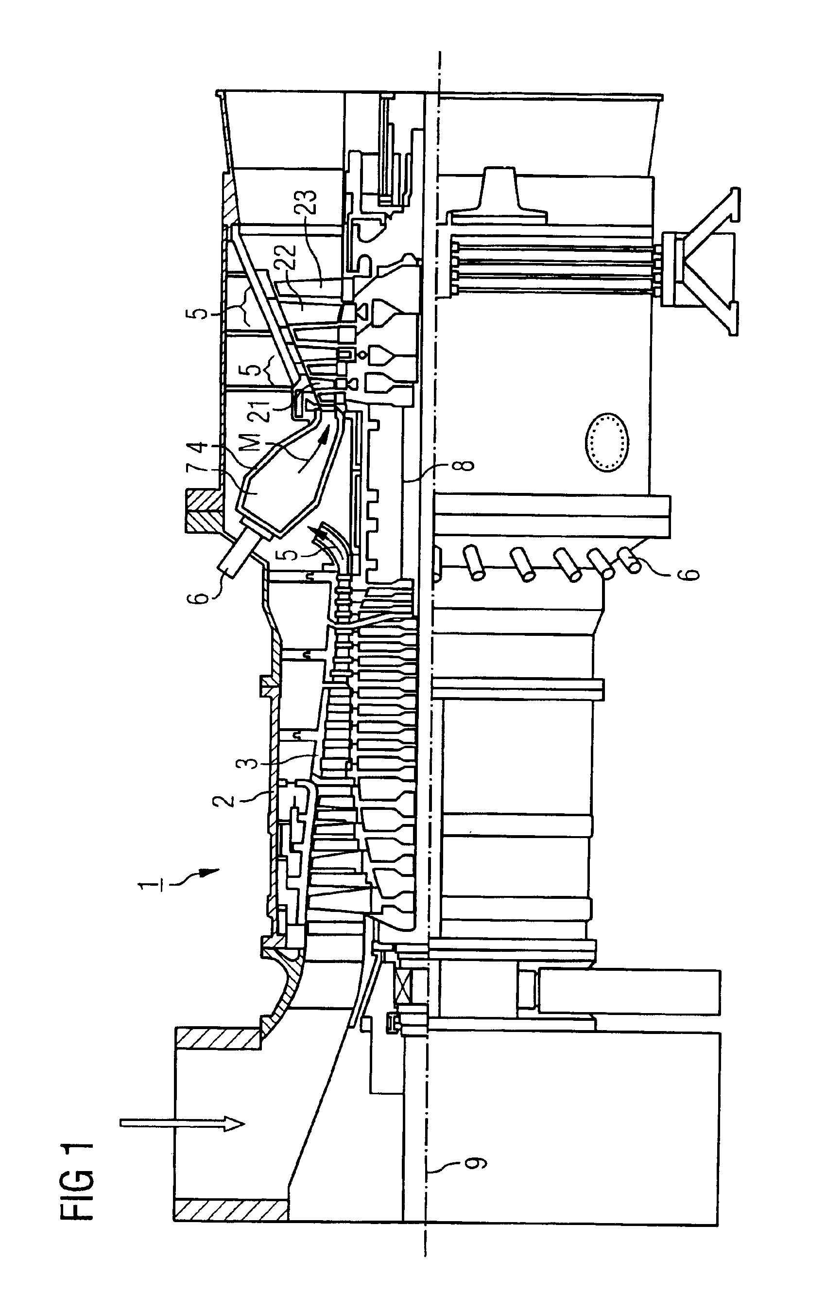
[0033]FIG. 1 shows a gas turbine 1 with a casing 2, a compressor 3, an annular combustion chamber 4, and several turbine stages 5 connected downstream of the annular combustion chamber 4. The air taken in by the compressor 3 is compressed in this and then forwarded to a burner 6. The compressed air is mixed there with a means of combustion and, on being injected into a combustor 7 located in the annular combustion chamber 4, is combusted to produce a working medium M. The working medium M then flows through a hot gas channel 21 past the turbine stages 5 each formed from a plurality of guide blades 22 and rotor blades 23 arranged separately in two rings. The energy of the working medium M is converted into rotational energy by means of the rotor blades 23 located on a rotor 8 mounted so it can rotate around the axis of rotation 9.

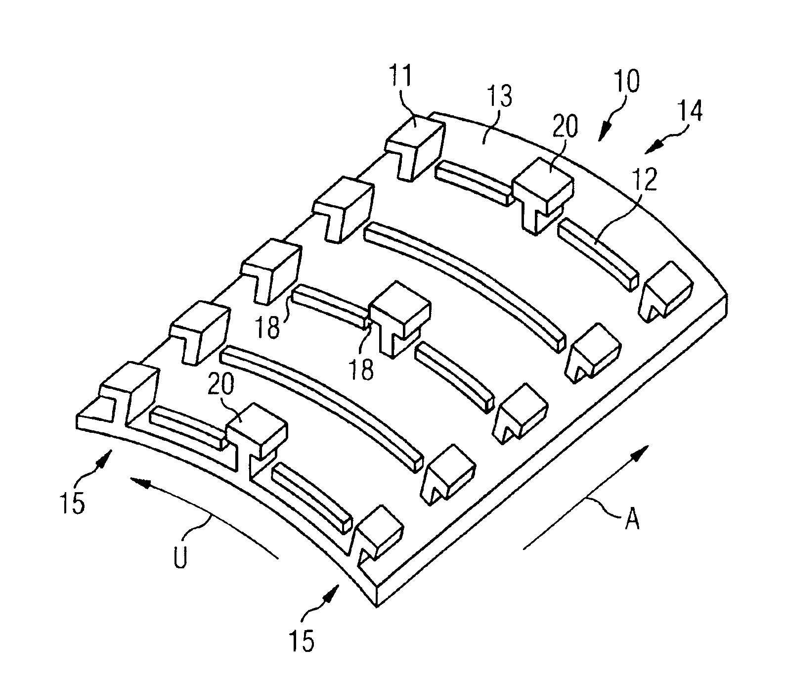
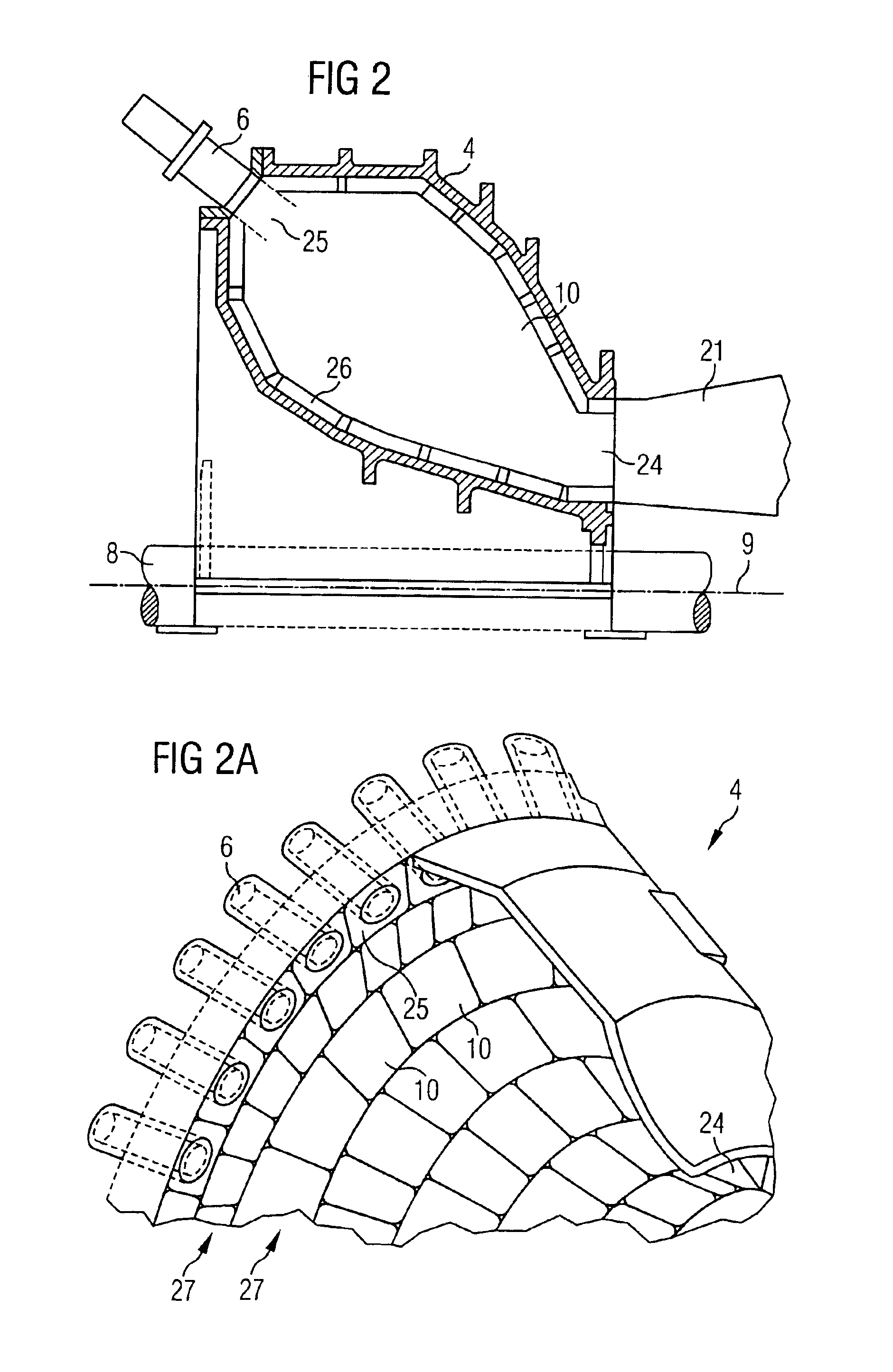
[0034]FIG. 2 shows a cross-section of an annular combustion chamber 4. The lower section of the annular combustion chamber 4 is not shown for reasons of sym...


PUM


Abstract

The invention relates to an annular combustion chamber for a gas turbine wherein the annular combustion chamber extends in an axial direction, encloses a combustor and has on its inside facing the combustor a bearing structure on which a lining element secured to this lines the annular combustion chamber. The object is to disclose an annular combustion chamber with a lining element that meets the mechanical requirements while at the same time taking account of the system's maintenance-friendliness. The object is achieved in that the annular combustion chamber has a lining element wherein on the rear side facing away from the combustor of two edge areas on the lining element a plurality of interlocking means are located which have a hook width and wherein the lining element is secured to the corresponding bearing structure such that in order to release the lining element from the bearing structure the lining element is moved by the extent of the hook width of the interlocking means in the axial direction.

Description

CROSS REFERENCE TO RELATED APPLICATIONS[0001]This application claims priority to the European application No. 02023471.2 EP, filed Oct. 21, 2002 under the European Patent Convention and which is incorporated by reference herein in its entirety.[0002]1. Field of the Invention[0003]The invention relates to an annular combustion chamber for a gas turbine wherein the annular combustion chamber extends in an axial direction, encloses a combustor, and has on its inside facing the combustor a bearing structure having a lining element secured to the bearing structure and lines the annular combustion chamber.[0004]2. Background of the Invention[0005]Gas turbines are nowadays often used to convert fossil energy in conjunction with a generator into electrical energy. The means of combustion is mixed with compressed air and routed to a combustor and combusted. The resulting working medium flows along a hot gas channel past several turbine stages. Each turbine stage consists of a plurality of gu...

Claims


Application Information

Patent Timeline
IPC IPC(8): F23R3/50F23R3/60F23R3/00F23M5/00F23M5/02F23M5/04F23R3/42F02C7/00F23R3/52
CPCF23M5/02F23M5/04F23R3/002F23R3/50F23R3/60
Inventor TIEMANN, PETER
Owner SIEMENS AG
Why Eureka
Try Eureka