Freestanding self-propelled device for moving objects

a self-propelled device and moving object technology, applied in the direction of wheelchairs/patient conveyances, tractors, cycles, etc., can solve problems such as physical injury to the mover, and achieve the effect of reducing back, shoulder and wrist strain

Inactive Publication Date: 2005-09-06
PIPP MOBILE STORAGE SYST
View PDF13 Cites 23 Cited by
  • Summary
  • Abstract
  • Description
  • Claims
  • Application Information

AI Technical Summary

Benefits of technology

[0006]The present invention provides a freestanding self-propelled device for moving objects, such as wheeled objects. The self-propelled device has a single drive wheel and can be attached to and used to move carts, beds or most any other equipment currently pushed or pulled by human operators. The device can be operated without significant physical effort by the operator, thereby eliminating back, shoulder and wrist strain when attempting to move large objects.
[0008]For stability and maneuverability of the device, the drive wheel is centrally located between first and second sets of support wheels coupled to the lower frame portion of the chassis. In combination, the drive wheel and the support wheels result in the self-propelled device being freestanding. However, the drive wheel projects below the first and second sets of support wheels so that the self-propelled device is supported by the drive wheel and by only one of the sets of support wheels at any given time, thereby establishing a three-point contact with the surface supporting the self-propelled device. The device is further equipped with a third set of support wheels mounted to the chassis and extending aft from the aft end of the chassis, so as to inhibit tipping of the self-propelled device in an aft direction thereof.
[0009]In view of the above, it can be seen that a significant advantage of this invention is that it can be attached to an object to be moved, such as a cart, bed, wheelchair, machine, or other equipment that may be equipped with wheels, and thereafter an operator can walk behind the device while operating the device through the controls on the tiller to move and maneuver the object. The device is both stable and highly maneuverable as a result of the arrangement of wheels supporting the chassis. As such, the self-propelled device of this invention is capable of moving large objects while significantly reducing the risk of stress to backs, shoulders, or wrists of workers who would otherwise be required to manually move such objects.

Problems solved by technology

However, movement in this manner can lead to physical injury to the mover, particularly in the case of large equipment.

Method used


Image

  • Freestanding self-propelled device for moving objects
  • Freestanding self-propelled device for moving objects
  • Freestanding self-propelled device for moving objects

Examples


Embodiment Construction

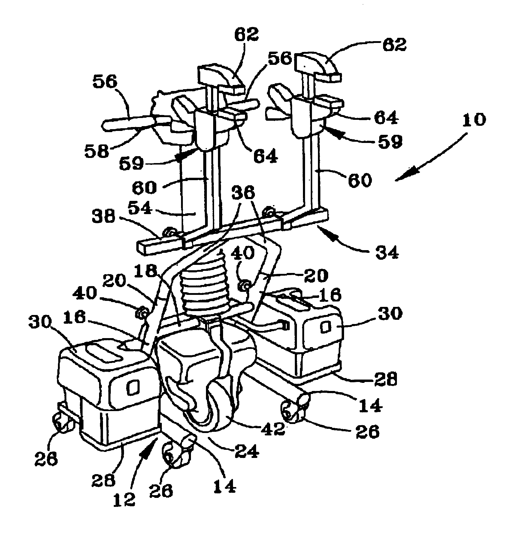
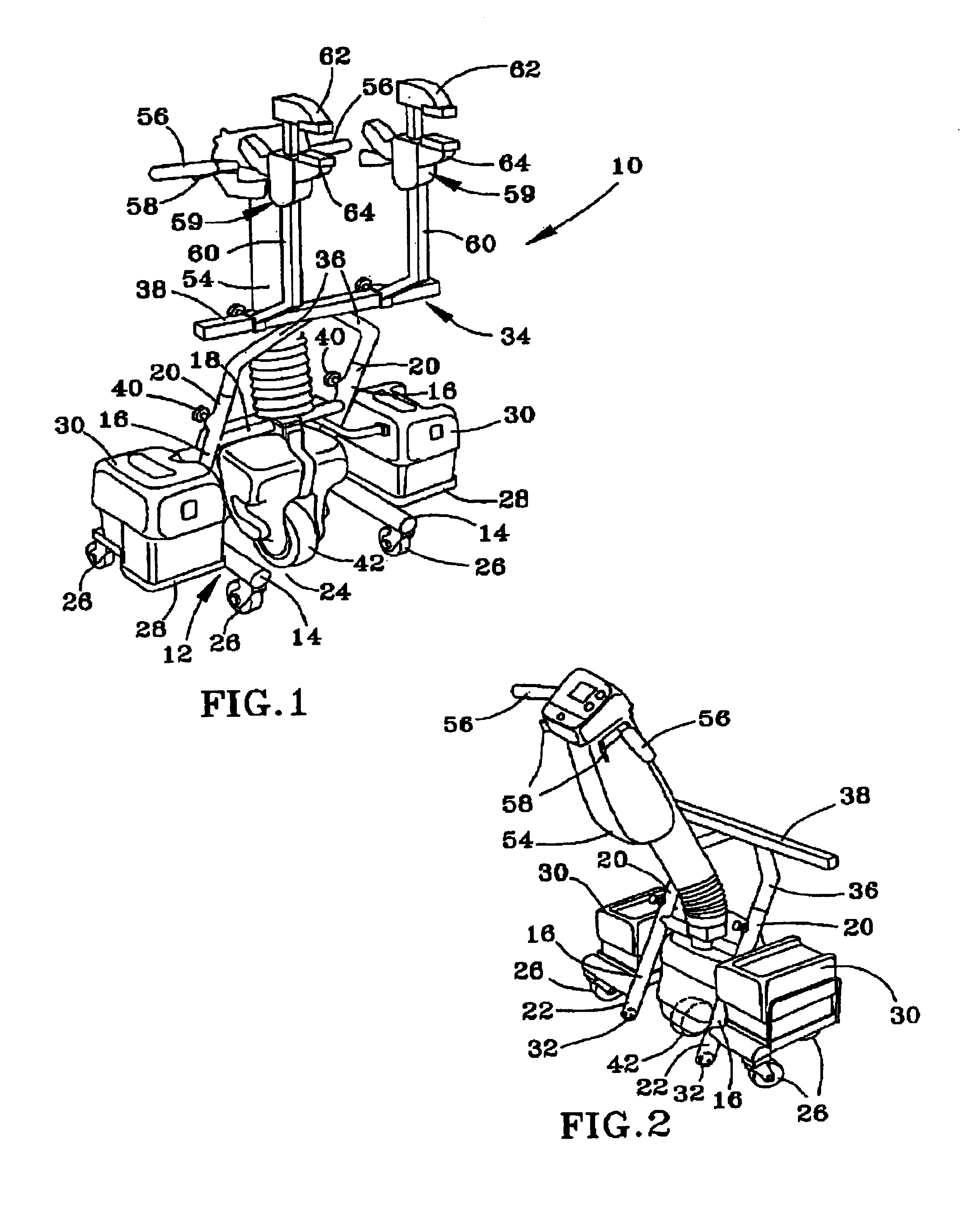
[0014]FIGS. 1 and 2 show a freestanding self-propelled moving device 10 in accordance with a preferred embodiment of this invention. As shown in the Figures, the device 10 comprises a chassis 12 that has a pair of lower frame members 14 that extend in the fore and aft directions of the device 10. A pair of hollow (e.g., tubular) upright frame members 16 are individually attached to the lower frame members 14, and a laterally-extending cross bar 18 interconnects midportions of the upright frame members 16. Each upright frame member 16 has an upper extremity 20 that projects above its corresponding lower frame member 14, and a lower extremity 22 that projects below its lower frame member 14. The upright frame members 16 are attached near their lower extremities 22 to their respective lower frame members 14 toward the aft end of the device 10. Furthermore, each upright frame member 16 is inclined in the fore direction of the device 10, preferably at an angle of about 64 degrees from ho...


PUM


Abstract

A freestanding self-propelled device for moving objects. The device includes a chassis having lower frame portions and upright frame portions. A single motor-driven drive wheel is centrally located between the lateral ends of the chassis and coupled to the chassis so as to be pivotable about a substantially vertical axis. The drive wheel is located between sets of support wheels coupled to the lower frame portion of the chassis. In combination, the drive wheel and the support wheels result in the device being freestanding. The drive wheel projects below the sets of support wheels so that the device is supported by the drive wheel and by only one of each set of support wheels at any given time, thereby establishing a three-point contact with the surface supporting the device. A tiller equipped with controls is pivotably coupled to the drive wheel for pivoting the drive wheel about its vertical axis.

Description

CROSS REFERENCE TO RELATED APPLICATIONS[0001]This application claims the benefit of U.S. Provisional Application No. 60 / 423,749, filed Nov. 6, 2002.BACKGROUND OF THE INVENTION[0002]1. Field of the Invention[0003]The present invention generally relates to devices for moving objects, such as wheeled carts, beds, equipment, etc., including those used in medical, food service and industrial facilities. More particularly, this invention relates to a freestanding device that uses a single battery-powered drive wheel and can be attached to and used to move an object without significant physical effort by the operator.[0004]2. Description of the Related Art[0005]Movement of carts, beds and miscellaneous other equipment in medical, food service, and industrial facilities is typically done by hand. For this reason, such objects are often equipped with caster wheels that permit their relocation by pushing and pulling. However, movement in this manner can lead to physical injury to the mover, p...

Claims


Application Information

Patent Timeline
Patent Type & Authority Patents(United States)
IPC IPC(8): B62D51/04B62D51/00
CPCB62D51/04A61G5/047
Inventor KIME, MARK CHANDLERJOHNSTON, RICHARD HARTLEY
Owner PIPP MOBILE STORAGE SYST
Why Eureka
Try Eureka