Loadbreak connector assembly which prevents switching flashover

a technology of load-breaking connectors and assembly parts, which is applied in the direction of one-pole connections, connection contact member materials, coupling device connections, etc., can solve the problems of flashover or arc to ground, reducing dielectric strength, and reducing pressure within the cavity

Inactive Publication Date: 2005-09-06
THOMAS & BETTS INT INC
View PDF70 Cites 55 Cited by
  • Summary
  • Abstract
  • Description
  • Claims
  • Application Information

AI Technical Summary

Benefits of technology

[0010]It is an object of the invention to provide loadbreak connectors, which upon disassembly under load, prevent flashover from occurring at the interface of the connectors.
[0011]It is a further object of the invention to provide a power cable elbow connector and loadbreak bushing insert having a modified interface which is vented to prevent a decrease in air pressure therebetween and a resulting decrease in dielectric strength of the air causing a flashover.
[0012]It is still a further object of the invention to provide a power cable elbow connector and loadbreak bushing insert having an indicator band formed on the bushing insert and which is vented to prevent a decrease in air pressure therebetween and a resulting decrease in dielectric strength of the air causing a flashover.

Problems solved by technology

During initial movement of the loadbreak connectors in the disassembly operation, the volume of air in the elbow cavity increases but is sealed off at the elbow cuff resulting in a decrease in pressure within the cavity.
Although this is a transient condition, it occurs at a critical point in the disassembly operation and can result in dielectric breakdown of the opening interface causing a flashover or arc to ground.
The lower pressure in the cavity reduces the dielectric strength of the air along the connection interface possibly resulting in flashover.
Another drawback with loadbreak connectors of the prior art is the difficulty involved in inserting one end of the loadbreak bushing insert into the power elbow connector and inserting the opposite end of the loadbreak bushing insert into a bushing well.

Method used


Image

  • Loadbreak connector assembly which prevents switching flashover
  • Loadbreak connector assembly which prevents switching flashover
  • Loadbreak connector assembly which prevents switching flashover

Examples


Embodiment Construction

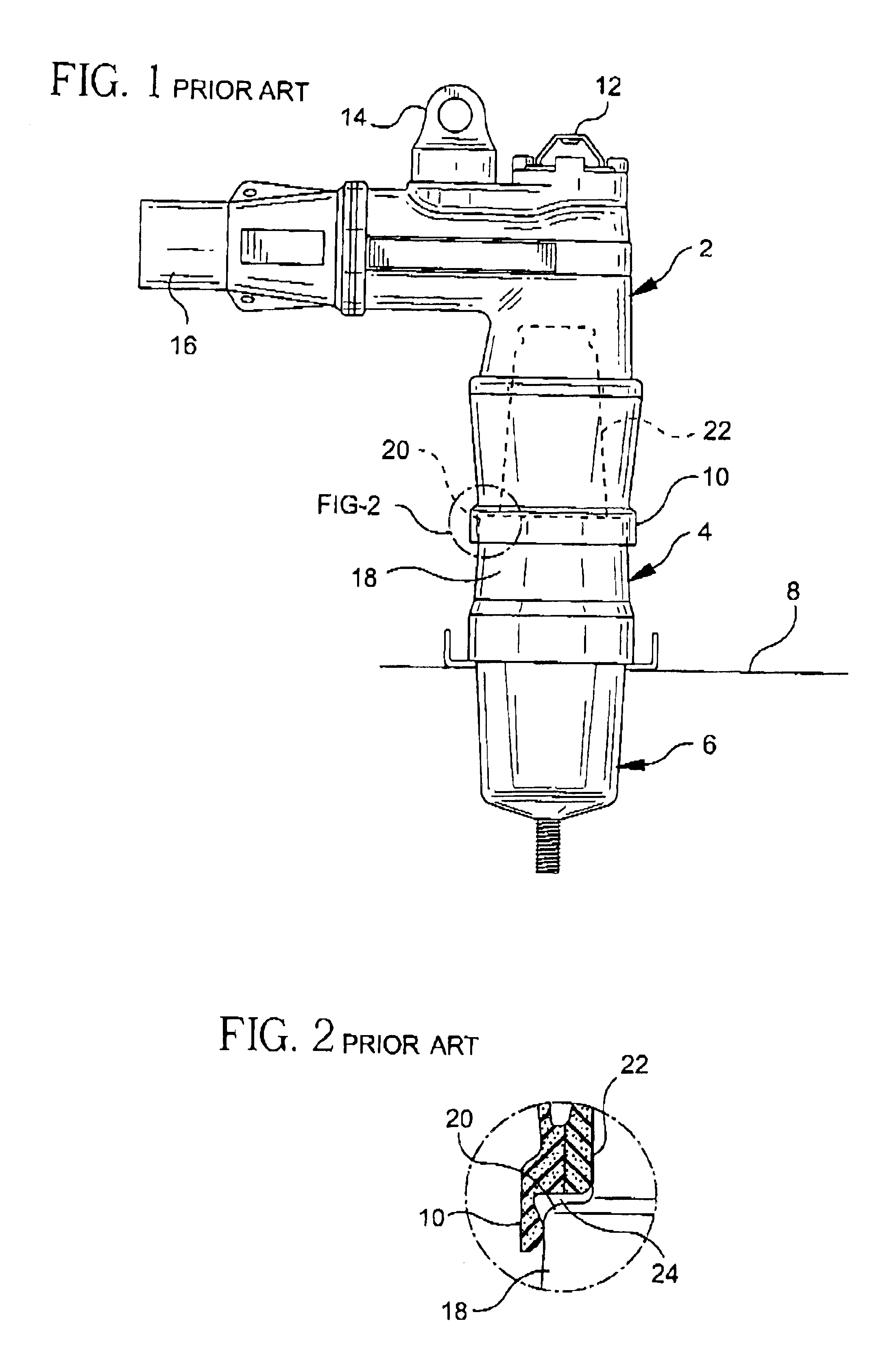
[0043]Referring to FIGS. 1 and 2, prior art loadbreak connectors are illustrated. In FIG. 1, a power cable elbow connector 2 is illustrated coupled to a loadbreak bushing insert 4 which is seated in a universal bushing well 6. The bushing well 6 is seated on an apparatus face plate 8. The power cable elbow connector 2 includes a first end adapted for receiving a loadbreak bushing insert 4 and having a flange or elbow cuff 10 surrounding the open receiving end thereof. The power cable elbow connector also includes an opening eye 12 for providing hot-stick operation and a test point 14 which is a capacitively coupled terminal used with appropriate voltage sensing devices. A power cable receiving end 16 is provided at the opposite end of the power cable elbow connector and a conductive member extends from the receiving end to the bushing insert receiving end for connection to a probe insertion end of the bushing insert.

[0044]Referring still to FIGS. 1 and 2, the loadbreak bushing inser...


PUM


Abstract

Loadbreak connectors which are modified to reduce the probability of flashover upon disassembly operation of a loadbreak bushing insert from a power cable elbow connector. The bushing insert is provided with vents to vent a cavity formed between the elbow cuff and the transition shoulder portion of the bushing insert with ambient air to avoid a decrease in pressure within the connection region and avoid a decrease in the dielectric strength of the air therein thus preventing flashover. The vents can be provided directly on the transition shoulder portion of the insert, an elbow seating indicator band or on a bushing insert interface shell. Additionally, the band and the shell may be formed of a bright contrasting color which serves to indicate whether the loadbreak connector is improperly assembled. The shell further reduces friction upon assembly of the connector.

Description

CROSS-REFERENCE TO RELATED U.S. APPLICATIONS[0001]This application is a continuation-in-part of U.S. application Ser. No. 09 / 715,571, filed on Nov. 17, 2000, now U.S. Pat. No. 6,585,531, which is a continuation of U.S. application Ser. No. 09 / 287,915, filed on Apr. 7, 1999, now U.S. Pat. No. 6,168,447, which is a continuation-in-part of Ser. No. 08 / 902,749, filed on Jul. 30, 1997, now U.S. Pat. No. 5,957,712.BACKGROUND OF THE INVENTION[0002]1. Field of the Invention[0003]The present invention relates to separable electrical connectors and more particularly to improvements in separable electrical connectors such as loadbreak connectors and deadbreak connectors, including a sleeve of low coefficient material for ease of connection / disconnection and which includes vents to prevent flashover upon switching (opening) the connectors.[0004]2. Description of the Prior Art[0005]Loadbreak connectors used in conjunction with 15 and 25 KV switchgear generally include a power cable elbow connect...

Claims


Application Information

Patent Timeline
Patent Type & Authority Patents(United States)
IPC IPC(8): H01R13/53H01R13/52H01R33/76H01R13/629H01R13/648H01R13/46H01R13/633H01R43/26
CPCH01R13/5216H01R13/53H01R43/26H01R13/629H01R2101/00H01R24/20H01R33/7678H01R13/648H01R13/633
Inventor BORGSTROM, ALAN D.STEPNIAK, FRANK M.SIEBENS, LARRY N.
Owner THOMAS & BETTS INT INC
Why Eureka
Try Eureka