Thoracic aortic stent graft deployment device

Active Publication Date: 2005-09-06
COOK MEDICAL TECH LLC +1
View PDF7 Cites 166 Cited by
  • Summary
  • Abstract
  • Description
  • Claims
  • Application Information

AI Technical Summary

Benefits of technology

[0013]There may be an arrangement which prevents movement of the sliding handle with respect to the moving handle until this movement is required. This arrangement may be provided by a thumbscrew fixed to the sliding handle which engages against a portion of the fixed handle to prevent inadvertent or early movement of the sliding handle with respect to the fixed handle. The thumbscrew is removed when it is desired to move the sliding handle.
[0014]There may also be provided a mechanism which prevents the deployment catheter from being moved forward after an initial movement back. Such a mechanism may be provided by a spring loaded pin or plunger mechanism on

Problems solved by technology

This can be done with a capsule, which covers the exposed stent, but there is a problem.
When withdrawing the capsule, a proximal end retention system, whic

Method used


Image

  • Thoracic aortic stent graft deployment device
  • Thoracic aortic stent graft deployment device
  • Thoracic aortic stent graft deployment device

Examples


Embodiment Construction

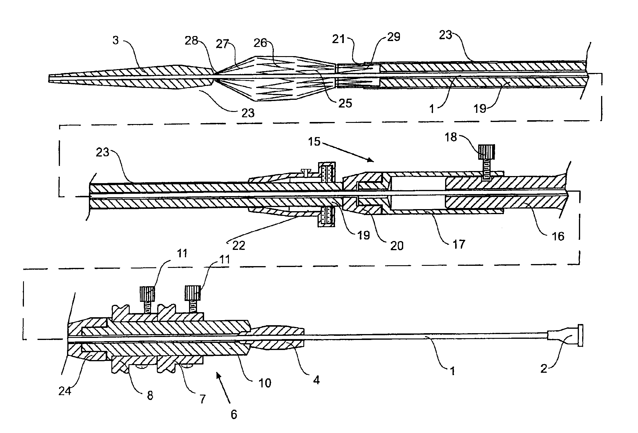
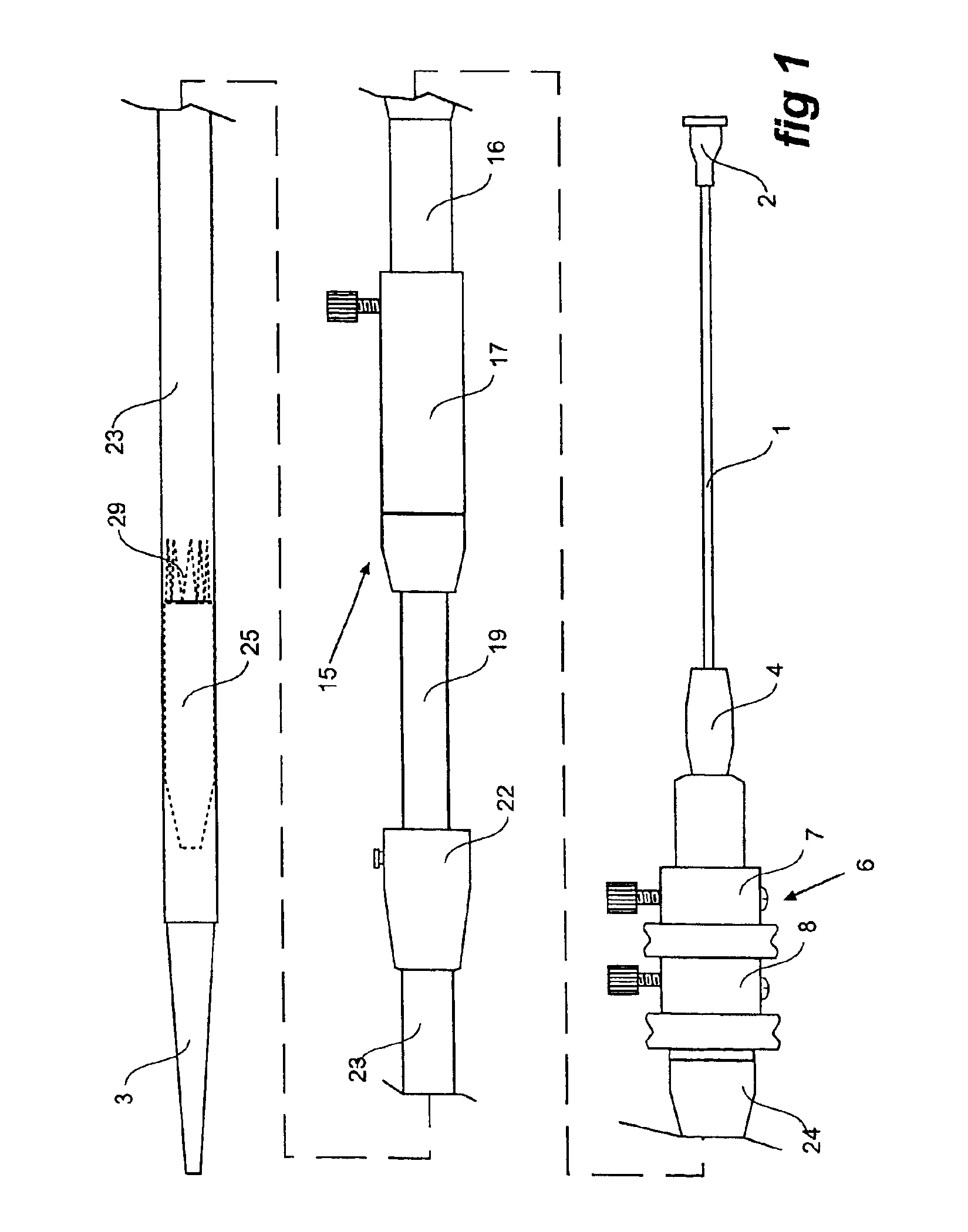
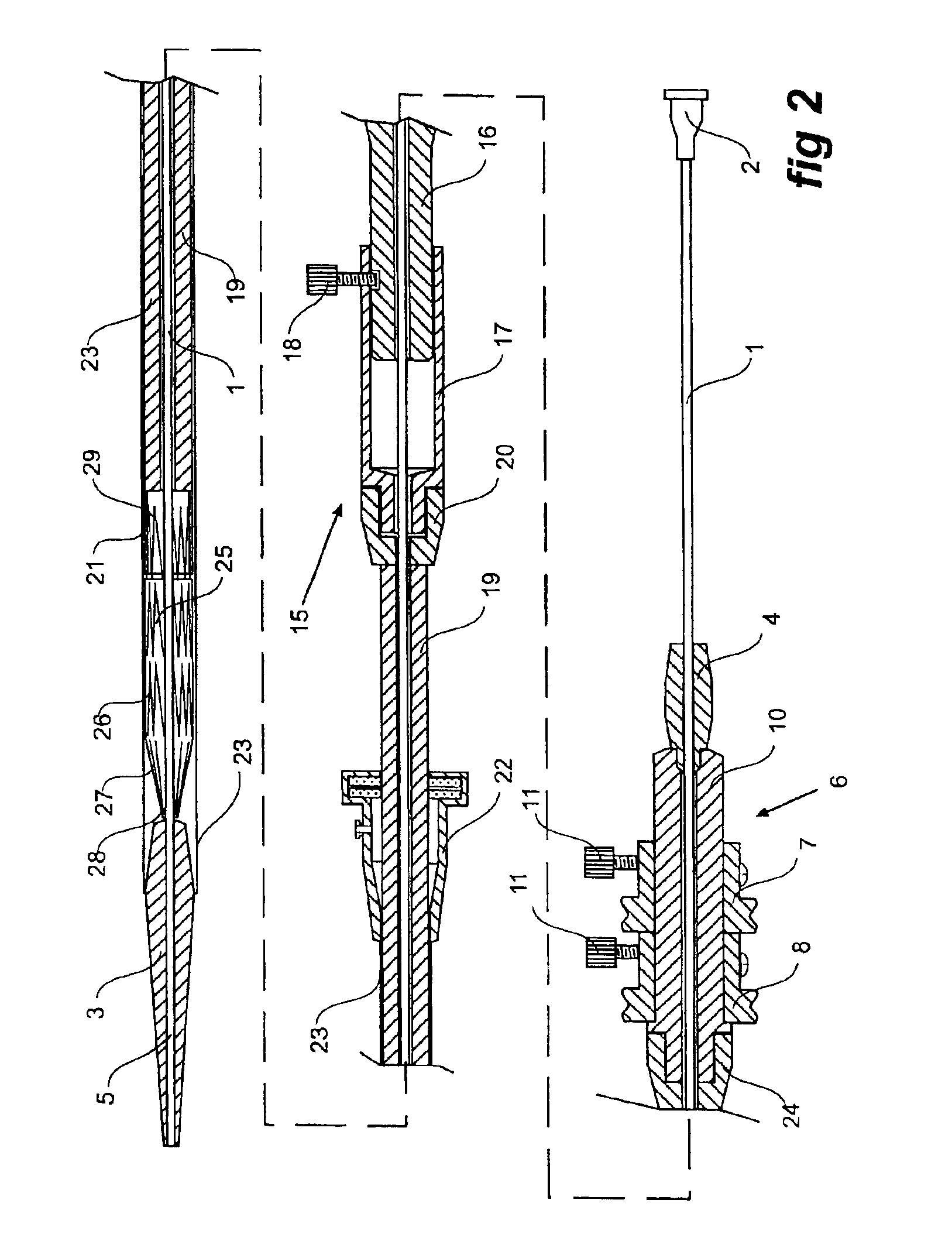
[0038]Now looking more closely at the drawings and in particular FIGS. 1 and 2, it will be seen that the deployment device generally comprises, working from the inside towards the outside, a guide wire catheter 1 which extends the full length of the device from a syringe socket 2 at the far distal end of the deployment device to a nose dilator 3 at the proximal end of the deployment device.

[0039]The nose cone dilator 3 is fixed to the guide wire catheter 1 and moves with it.

[0040]The nose cone dilator has a through bore 5 as an extension of the lumen of the guide wire catheter 1 so that the deployment device can be deployed over a guide wire (not shown).

[0041]To lock the guide wire catheter 1 with respect to the deployment device in general, a pin vice 4 is provided.

[0042]The trigger wire release mechanism generally shown as 6 at the distal end of the deployment device includes a distal end trigger wire release mechanism 7 and a proximal end trigger wire release mechanism 8. The tri...


PUM


Abstract

A stent graft deployment device adapted for release of a distal end (29) of a stent graft (25) before the proximal end (27) of the stent graft (25). The arrangement (15) allows movement of at least part of the deployment catheter (23) independently of movement of a proximal end release mechanism has a fixed handle (16) associated with a trigger wire release mechanism (6) and a sliding handle (17) to which the deployment catheter and a capsule (21) are fixed. The sliding handle (17) is mounted on the fixed handle (16) and can slide longitudinally with respect to the fixed handle (16).

Description

CROSS-REFERENCE TO RELATED APPLICATIONS[0001]This application claims priority to provisional application Ser. No. 60 / 392,667, filed Jun. 28, 2002. This application is also related to provisional application Ser. No. 60 / 391,737, filed Jun. 26, 2002, and entitled “Stent-Graft Fastening Arrangement.”TECHNICAL FIELD[0002]This invention relates to a device for the deployment of a stent graft within the aorta and particularly in relation to deployment within the thoracic aorta.BACKGROUND OF THE INVENTION[0003]Throughout this specification when referring to deployment of a stent graft or prosthesis within the aorta of a patient the term proximal will be used for that end of both the deployment device and the stent graft at that end which is closer to the heart of a patient and the term distal will be used for that end of the deployment device or stent graft which in use is furthest from the heart. When applied to other vessels corresponding terms such as caudal and cranial should be unders...

Claims


Application Information

Patent Timeline
IPC IPC(8): A61F2/06A61F2/84
CPCA61F2/95A61F2/07A61F2/958A61F2/966A61F2002/9517A61F2/9517
Inventor HARTLEY, DAVID ERNESTHUFFER, LEIGH ANTHONY
Owner COOK MEDICAL TECH LLC
Why Eureka
Try Eureka