Method and apparatus for determining the mass of an article using a load cell

a technology of mass determination and load cell, which is applied in the direction of instrumentation, measurement devices, ticket-issuers, etc., can solve the problems of large transport, high acceleration and deceleration rate, and slow development of weighing devices for such mail processing systems

Inactive Publication Date: 2005-09-06
PITNEY BOWES INC
View PDF12 Cites 46 Cited by
  • Summary
  • Abstract
  • Description
  • Claims
  • Application Information

AI Technical Summary

Problems solved by technology

Heretofore, weighing devices for such mail processing systems have been developed, but these generall...

Method used


Image

  • Method and apparatus for determining the mass of an article using a load cell
  • Method and apparatus for determining the mass of an article using a load cell
  • Method and apparatus for determining the mass of an article using a load cell

Examples


Embodiment Construction

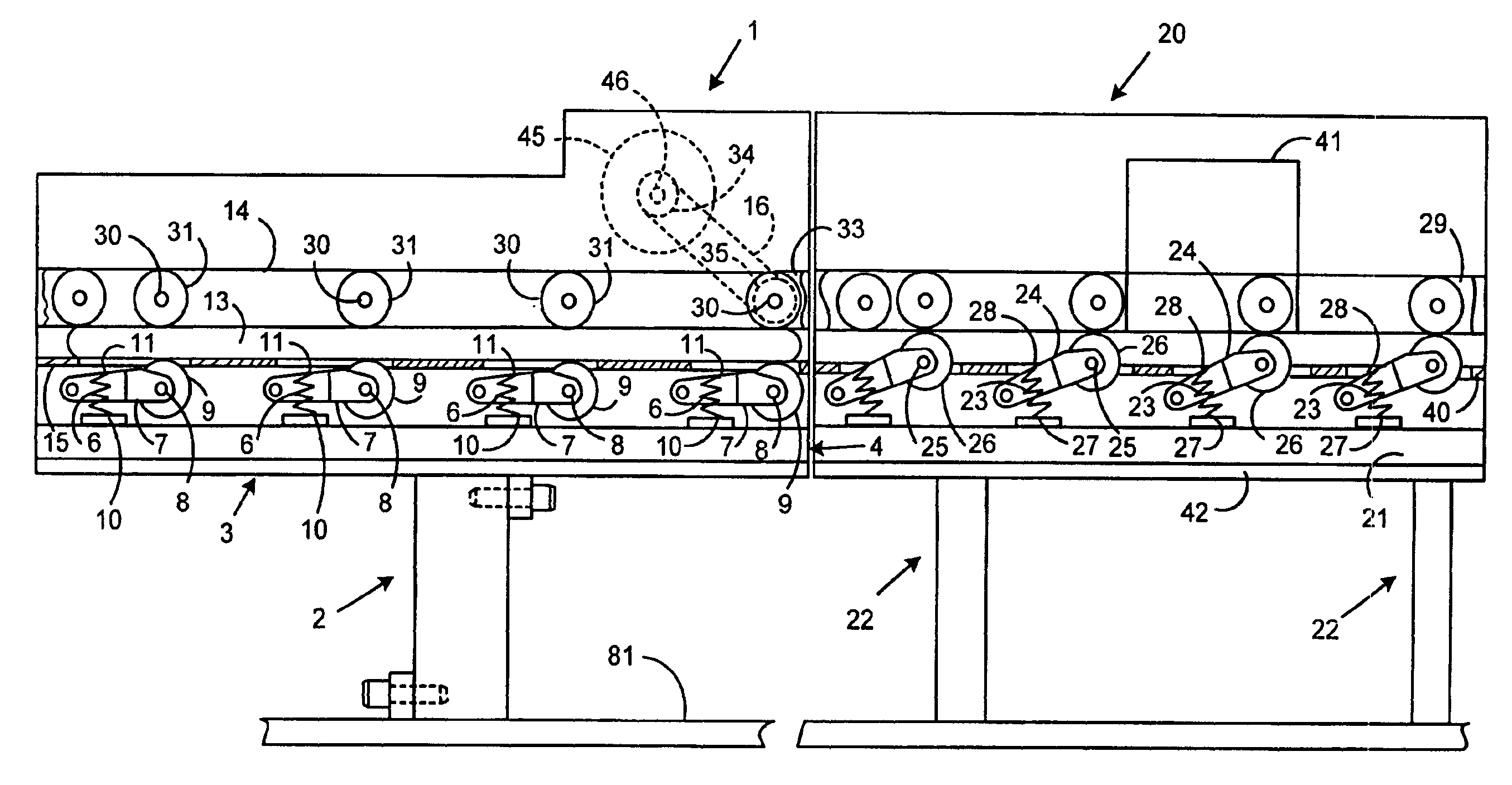
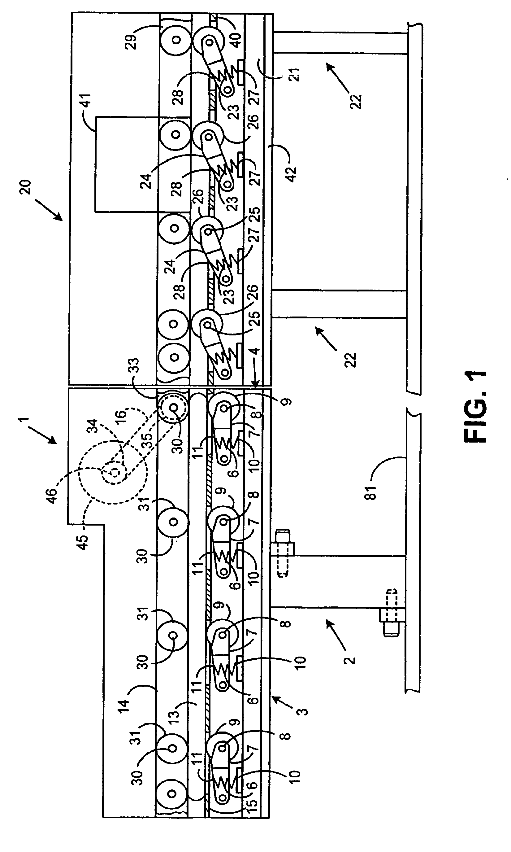
[0012]FIG. 1 illustrates the weighing conveyor 1 of the present invention. The conveyor 1 is interposed between a suitable feeding module (not shown) from which mail pieces 13 are fed seriatim to the weighing conveyor 1 where they are weighed prior to a postage indicia being printed thereon by a postage meter module 20. The weighing conveyor 1 is comprised of a load cell 2 and a resilient base 81. Preferably base 81 is formed of a vibration damping material, as is taught in U.S. Pat. No. 4,479,561, to Feinland et al. Thus, as mail piece 13 is transported, external vibrations are not felt by the load cell 2 but are isolated from ground by base 81. Such a system is described, for example, in commonly assigned U.S. Pat. No. 5,082,072 which is hereby incorporated by reference.

[0013]With reference to FIG. 1, the weighing conveyer 1 is provided with a load cell 2 fixedly mounted to frame 3. Secured to the upper end of frame 3 is a bracket 4 which supports a platform 15 for receiving a mai...


PUM


Abstract

A method of determining the mass of an article using a load cell. An article whose mass is to be determined is transported across a platform without stopping or slowing the article. A load cell measures the horizontal force applied to the load cell by the transported article. This horizontal force, along with the acceleration of the article, allows a determination of the mass of the article.

Description

BACKGROUND OF THE INVENTION[0001]The subject invention relates to a method for rapidly determining the mass of a mail piece.[0002]Mailing systems where a mail piece is transported onto a postal scale, the appropriate postage is determined and used to set a postage meter, and the mail piece is then transported to the postage meter for imprinting with a postal indicia representative of the postage amount are known. One such system is described in U.S. Pat. No. 4,742,878, issued May 10, 1988 to the assignee of the subject invention. In such systems, there is a constant need to increase the rate at which the scale can determine the mass of a mail piece in order that the throughput of the system can be increased. Heretofore, weighing devices for such mail processing systems have been developed, but these generally have been rather slow. Actually, many prior weight devices combined a standard scale with a mechanism that would stop the mail to allow weighing to take place. These systems re...

Claims


Application Information

Patent Timeline
IPC IPC(8): G01G19/00G01G19/22G01G9/00G07B17/00
CPCG01G19/005G07B2017/00701
Inventor SALOMON, JAMES A.
Owner PITNEY BOWES INC
Why Eureka
Try Eureka