PWM-based DC-DC converter with assured dead time control exhibiting no shoot-through current and independent of type of FET used

a dc-dc converter and dead time control technology, applied in pulse generators, pulse techniques, instruments, etc., can solve problems such as insufficient dead tim

Active Publication Date: 2005-09-06
INTERSIL INC
View PDF9 Cites 34 Cited by
  • Summary
  • Abstract
  • Description
  • Claims
  • Application Information

AI Technical Summary

Benefits of technology

[0009]A first case corresponds to the polarity of the voltage at the PHASE node going negative after the LGATE node transitions from high-to-low. In response to the LGATE voltage going low, the voltage at the PHASE node is monitored to determine whether it has reached a prescribed negative polarity voltage (e.g., −0.4 V). In particular, following a blanking delay, if the phase voltage at the PHASE node drops below the −0.4 V threshold, combinational logic triggers a low-to-high to transition on the UGATE, which causes the phase node voltage to go high.
[0010]The second case is associated with a reverse current condition, and corresponds to the polarity of the voltage at the PHASE node going positive subsequent to the LGATE node transitioning from high-to-low. For this purpose, if Case I is not observed, namely, if the −0.4 V threshold is not reached following the high-to-low transition of the LGATE voltage, combinational logic looks to see whether a prescribed positive threshold (e.g., +0.6 V) has been reached. If so, the combinational logic will trigger a low-to-high transition of the UGATE signal, which causes the phase node voltage to go high.
[0011]The third case associated with a no load condition, corresponds to the elapse of a prescribed time-out without either of the positive and negative polarity thresholds having been reached at the phase node. Namely, if neither the −0.4 V and +0.6 V thresholds is observed at the phase node within a prescribed time out window after the high-to-low transition in the LGATE signal, the combination logic triggers a low-to-high transition of the UGATE signal so that the voltage at the phase node goes high.
[0012]A comparison of the LGATE turn-off transition with the respective UGATE turn-on tr

Problems solved by technology

This unwanted intermittent conduction problem results from i

Method used


Image

  • PWM-based DC-DC converter with assured dead time control exhibiting no shoot-through current and independent of type of FET used
  • PWM-based DC-DC converter with assured dead time control exhibiting no shoot-through current and independent of type of FET used
  • PWM-based DC-DC converter with assured dead time control exhibiting no shoot-through current and independent of type of FET used

Examples


Embodiment Construction

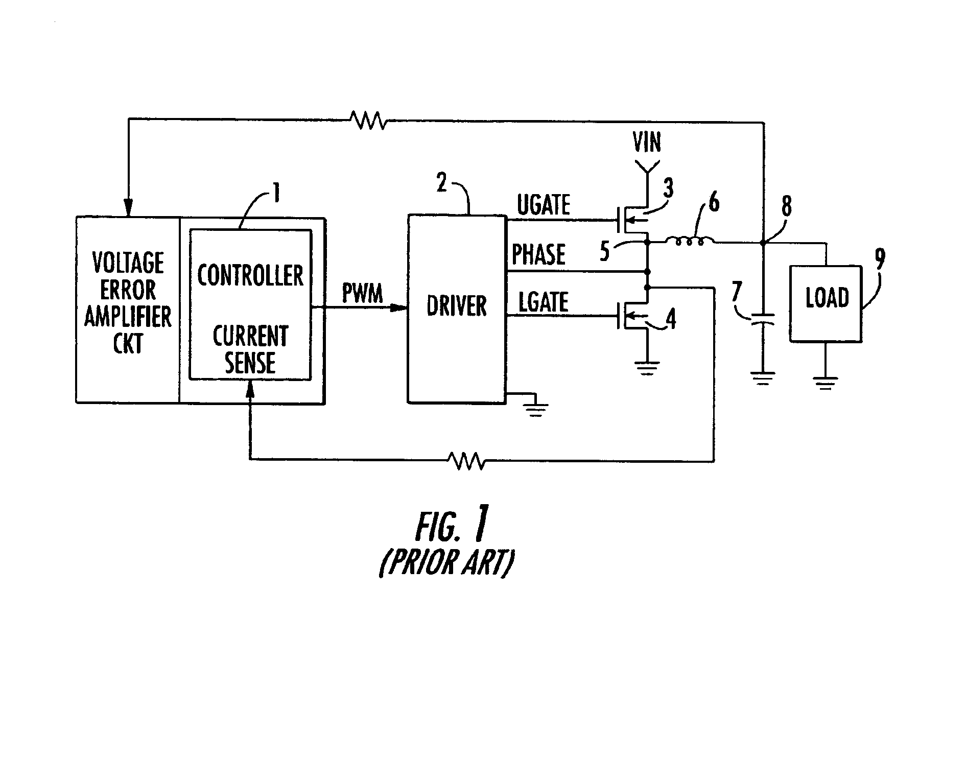
[0019]Before describing in detail the PWM-based DC-DC converter circuit in accordance with the present invention, it should be observed that the invention resides primarily in a prescribed modular arrangement of conventional circuits and components therefor. In a practical implementation that facilitates their being packaged in a hardware-efficient configuration, this arrangement may be readily implemented as a field programmable gate array (FPGA), or application specific integrated circuit (ASIC) chip set. Consequently, the configuration of such arrangement of circuits and components and the manner in which they are interfaced with other electronic circuitry have, for the most part, been illustrated in the drawings by readily understandable block diagrams, which show only those specific details that are pertinent to the present invention, so as not to obscure the disclosure with details which will be readily apparent to those skilled in the art having the benefit of the description...


PUM


Abstract

A control circuit for a switch mode DC-DC converter contains an arrangement of monitored LGATE, UGATE and PHASE node condition threshold detectors, outputs of which are processed in accordance with a switching control operator to ensure that each of an upper FET (UFET) and a lower FET (LFET) is completely turned off before the other FET begins conduction, thereby maintaining a dead time that exhibits no shoot-through current and is independent of the type of switching FET.

Description

CROSS-REFERENCE TO RELATED APPLICATION[0001]The Present Application claims the benefit of co-pending U.S. Patent Application Ser. No. 60 / 437,180 filed Dec. 31, 2002, by N. Dequina et al, entitled: “Assured Dead Time Control Exhibiting No Shoot-Through Current and Independent of Type of FET Used,” assigned to the assignee of the present application and the disclosure of which is incorporated herein.FIELD OF THE INVENTION[0002]The present invention relates in general to DC power supply circuits and components therefor, and is particularly directed to a new and improved pulse width modulator (PWM)-based DC-DC converter circuit, that is configured to maintain a fixed dead time that exhibits no shoot-through current and is independent of the type of switching FET used.BACKGROUND OF THE INVENTION[0003]Electrical power for an integrated circuit (IC) is typically supplied by one or more direct current (battery) power sources, such as a pulse width modulation (PWM)-based, DC-DC converter. As...

Claims


Application Information

Patent Timeline
IPC IPC(8): H02M1/00H02M3/158H02M3/04
CPCH02M1/38H02M3/1588Y02B70/1466Y02B70/10
Inventor DEQUINA, NOELPRESLAR, DONALD R.SFERRAZZA, PAUL K.
Owner INTERSIL INC
Why Eureka
Try Eureka