Methods and apparatus for duty cycle control

a technology of duty cycle and control method, applied in the field of electronic circuits, can solve problems such as difficulty or inability to maintain, distorted duty cycle, and disruption of system operation

Inactive Publication Date: 2005-09-06
MOSAID TECH
View PDF6 Cites 75 Cited by
  • Summary
  • Abstract
  • Description
  • Claims
  • Application Information

AI Technical Summary

Problems solved by technology

The duty cycle may be distorted, however, due to variations in signal propagation paths and other factors.
Thus, an intended 50% duty cycle may become skewed in operation, which may disrupt the proper operation of the system.
Such systems, however, require maintenance of the reference voltage at a constant level, which may be difficult or impossible to maintain.
Further, such circuits require time to settle to the proper duty cycle, and may be sensitive to noise as well.

Method used


Image

  • Methods and apparatus for duty cycle control
  • Methods and apparatus for duty cycle control
  • Methods and apparatus for duty cycle control

Examples


Embodiment Construction

[0015]Various aspects and features of the present invention may be described in terms of functional components and steps. Such functional components and steps may be realized by any number of elements and / or steps configured to perform the specified functions. For example, the present methods and apparatus may employ electronic, signaling, and logic elements, like capacitors, resistances, transistors, buffers, operational amplifiers, and voltage supplies, that may carry out a variety of functions in various embodiments, applications, and environments. In addition, the present methods and apparatus may be practiced in conjunction with any number of procedures and systems, and the apparatus and methods described are merely exemplary applications for the invention. Further, the methods and apparatus may employ any appropriate techniques, conventional or otherwise, for placement, use, manufacturing, and the like.

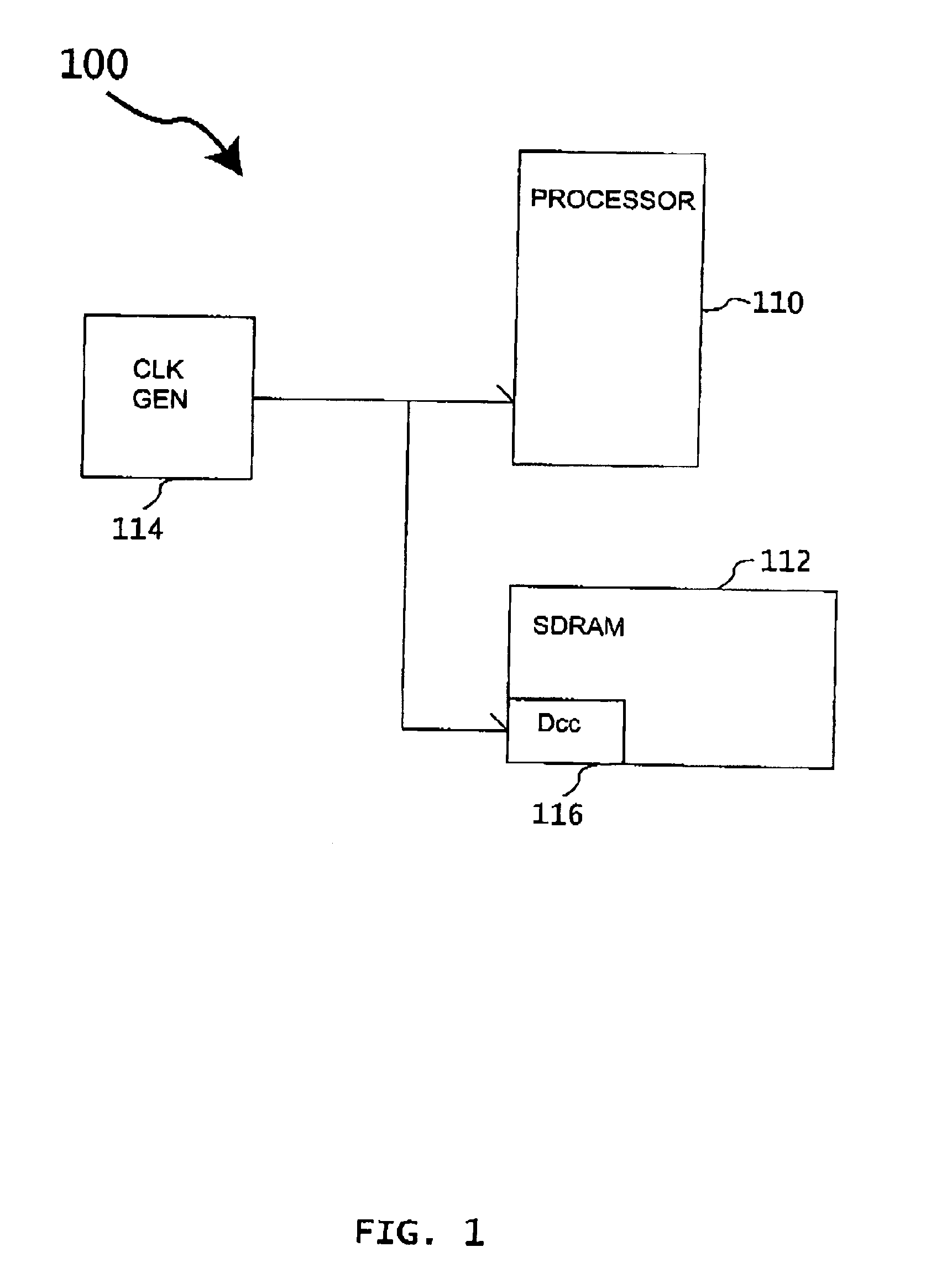
[0016]An electronic system according to various aspects of the present inve...


PUM


Abstract

An electronic system according to various aspects of the present invention comprises a signal generator configured to generate a first signal and a duty cycle correction circuit configured to be responsive to the first signal and provide a corrected signal having a corrected duty cycle. The duty cycle correction circuit may include a duty cycle detection circuit and a signal adjustment circuit. The duty cycle detection circuit is suitably configured to identify a disparity between a corrected duty cycle of the corrected signal and a target duty cycle. In one embodiment, the duty cycle detection circuit includes a self-bias circuit configured to generate a control signal according to the disparity between the corrected duty cycle and the target duty cycle. The signal adjustment circuit may be responsive to the control signal and configured to provide the corrected signal having the corrected duty cycle according to the control signal.

Description

FIELD OF THE INVENTION[0001]The present invention generally relates to electronic circuits.BACKGROUND OF THE INVENTION[0002]Many high-speed electronic systems utilize both the rising and falling edges of a clock signal to double the speed of the system without doubling the clock rate. In such systems, the proper duty cycle of the clock signal is critical, for example to latch data at the appropriate time. The duty cycle may be distorted, however, due to variations in signal propagation paths and other factors. Thus, an intended 50% duty cycle may become skewed in operation, which may disrupt the proper operation of the system.[0003]Many systems include a duty cycle correction circuit to maintain the desired duty cycle. Referring to FIG. 8, a conventional duty cycle corrector comprises three stages. Typically, a duty cycle detector 710 uses a capacitor to convert the duty cycle information into an analog signal having a magnitude proportional to the duty cycle difference. The differe...

Claims


Application Information

Patent Timeline
Patent Type & Authority Patents(United States)
IPC IPC(8): H03K3/00H03K5/04H03K3/017H03K5/156
CPCH03K5/1565
Inventor LIN, FENG
Owner MOSAID TECH
Why Eureka
Try Eureka