PLL frequency synthesizer using charge pump

Inactive Publication Date: 2005-09-06
LENOVO INNOVATIONS LTD HONG KONG
View PDF23 Cites 9 Cited by
  • Summary
  • Abstract
  • Description
  • Claims
  • Application Information

AI Technical Summary

Benefits of technology

[0008]The present invention has been made in view of the foregoing problems of the prior art, and has as its object to provide a PLL frequency synthesizer for reducing the possibility of disturbing the drain / absorption balance of a charge pump in the PLL frequency synthesizer using the charge pump.
[0011]In the PLL frequency synthesizer having this arrangement, when the output voltage and output current of the charge pump come close to their driving limits, the power supply voltage of the VCO automatically changes to cancel a change in input voltage of the VCO. This enables the PLL to operate very stably.
[0013]In the prior art, when the control voltage of the VCO is close to the power supply voltage or ground, the VCO itself may decrease in frequency sensitivity or stop oscillating. However, the present invention can reduce the possibility of causing these phenomena.
[0015]Accordingly, the output voltage of the charge pump does not go extremely high or low. Especially in a current-driven charge pump, currents generated by drain operation and absorption operation reduce. When the PLL is steady, small currents generated by these operations also reduce. Even the output frequency deviation of the VCO 6 is expected to reduce.
[0016]Further, according to the present invention, the input voltage of the VCO does not come very close to the power supply voltage or ground. Oscillation of the VCO can be prevented from stopping, and changes in frequency sensitivity by a change in input voltage can be suppressed.

Problems solved by technology

However, when a voltage at the output terminal of the charge pump comes close to the power supply voltage or ground voltage, the DC bias of an element (generally using an FET) for performing drain / absorption operation upon reception of a signal from the phase comparator greatly changes to disturb the drain / absorption balance.
However, the phase comparator itself is integrated into an IC, so it is not practical in consideration of the current popularity of synthesizer ICs to control the power supply of only the phase comparator.

Method used


Image

  • PLL frequency synthesizer using charge pump
  • PLL frequency synthesizer using charge pump
  • PLL frequency synthesizer using charge pump

Examples


Embodiment Construction

[0024]An embodiment of the present invention will be described below with reference to the accompanying drawings.

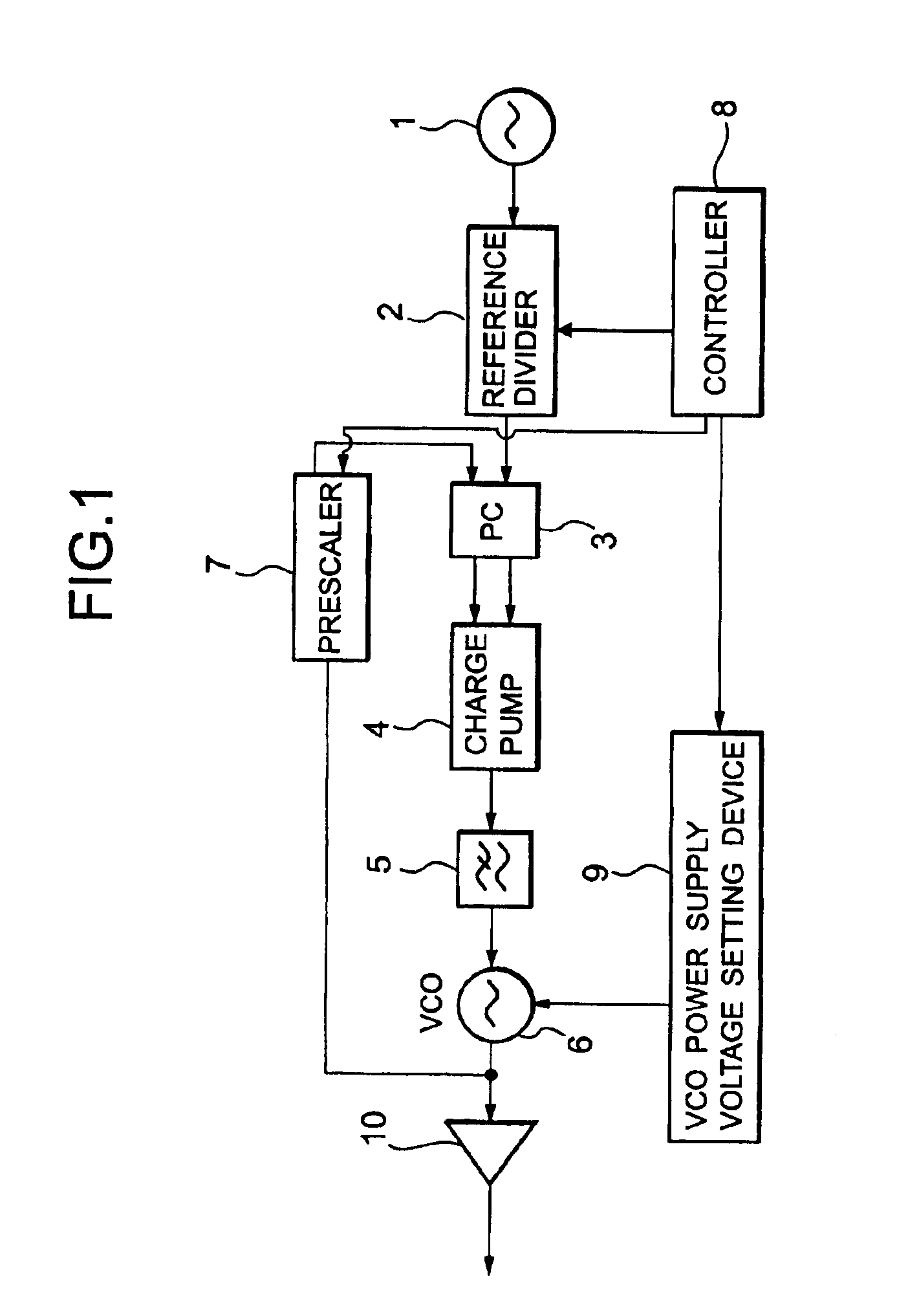
[0025]FIG. 1 is a block diagram showing the circuit of a PLL frequency synthesizer according to the embodiment of the present invention.

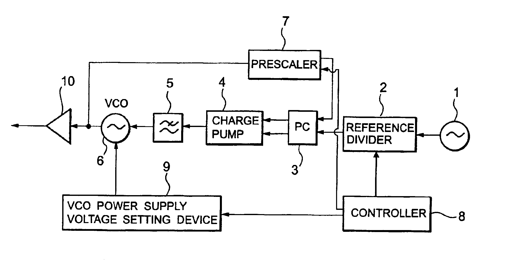
[0026]As shown in FIG. 1, this circuit comprises a reference frequency generator 1, reference divider 2, phase comparator 3, charge pump 4, low-pass filter (LPF) 5, voltage-controlled oscillator (VCO) 6, prescaler 7, controller 8, VCO power supply voltage setting device 9, and buffer amplifier 10. The circuit outputs a frequency switchable by the controller 8.

[0027]A reference signal generated by the reference frequency generator 1 is divided by the reference divider 2. The VCO 6 generates an output signal having a frequency corresponding to the voltage value of a control voltage output from the LPF 5. The generated signal branches to the buffer amplifier 10 and prescaler 7, and is frequency-divided by the prescaler 7.

[0028]The signal fre...


PUM


Abstract

In order to reduce the possibility of disturbing the drain / absorption balance of a charge pump in the PLL frequency synthesizer using the charge pump, when the output voltage and output current of the charge pump come close to their driving limits, the power supply voltage of a voltage-controlled oscillator is changed to cancel a change in input voltage of the voltage-controlled oscillator.

Description

BACKGROUND OF THE INVENTION[0001]1. Field of the Invention[0002]The present invention relates to a PLL frequency synthesizer, and more particularly to a PLL frequency synthesizer for driving a charge pump using an output from a phase comparator for comparing a phase of a frequency of a generation voltage of a voltage-controlled oscillator with a phase of a reference frequency, and driving the voltage-controlled oscillator using an output from the charge pump, thereby outputting a signal having a set desired frequency.[0003]2. Description of the Prior Art[0004]A generally used PLL frequency synthesizer drives a charge pump using an output from a phase comparator, and drives a VCO using an output from the charge pump. The charge pump can be driven by various methods. The mainstream current drains or absorbs current to or from the charge pump in accordance with an output from the phase comparator.[0005]The charge pump constituted in this manner can easily increase the current value wit...

Claims


Application Information

Patent Timeline
IPC IPC(8): H03L7/08H03L7/089H03L7/10H03L7/16H03L7/187H03L7/099H03L7/18
CPCH03L7/0891H03L7/10H03L7/187H03L7/099H03L2207/06H03L7/104
Inventor ISHII, KATSUHIRO
Owner LENOVO INNOVATIONS LTD HONG KONG
Why Eureka
Try Eureka