Allocation of channels to radio transceivers

a technology of radio transceivers and channels, applied in the field of allocation of channels to radio transceivers, can solve the problems of insufficient such channels, liable to interference, and possible interference between phone calls, and achieve the effect of avoiding inaccuracy and reducing the effort of compiling the tabl

Inactive Publication Date: 2005-09-06
BRITISH TELECOMM PLC
View PDF8 Cites 23 Cited by
  • Summary
  • Abstract
  • Description
  • Claims
  • Application Information

AI Technical Summary

Benefits of technology

[0023]The exemplary embodiment removes the need for, and reliance on, a table of interference strength coefficien...

Problems solved by technology

Each operator is permitted to use a limited number of radio channels, and there are not enough such channels for each phone call in the network to be carried on a different channel.
This introduces the possibility of interference between phone calls.
‘Adjacent channel’ interference, due to another call using a different channel, is also a problem: a call made on a channel corresponding to a frequency band of 4000-4025 kHz is liable to interference from a call on the adjacent band; 4025-4050 kHz.
Adjacent channel interference can occur between two calls in the same cell, as well as between adjacent cells.
The problem facing the network operator is to allocate channels to base stations such that demand for channels across the network is met, while keeping interference within acceptable levels.
These aims are clearly in conflict: if more channels are allocated to each base station, then each channel must be used by more base stations, and so it is harder to plan to avoid unacceptable interference.
An added difficulty is that the demand across the network is neither uniform nor static.
Even worse, for efficient channel allocation, are the unpredictable fluctuations in dema...

Method used


Image

  • Allocation of channels to radio transceivers
  • Allocation of channels to radio transceivers
  • Allocation of channels to radio transceivers

Examples


Embodiment Construction

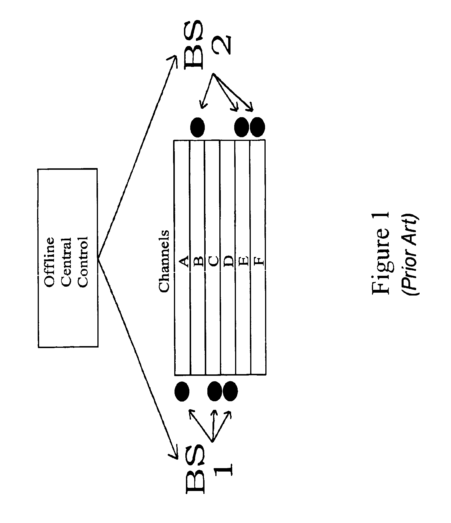
[0032]In FIGS. 1 to 3 two base station transceivers BS1, BS2 are shown, which both have access to six traffic channels A,B,C,D,E,F. In the Prior Art system of FIG. 1 a central controller determines the optimal allocation. This happens ‘offline’ based on interference and blocking data collected over a period of time. The optimal allocation is then imposed on the network. The optimal allocation is indicated by the markers in FIG. 1, in which Channels A,C,D are allocated to BS1 and channels B,E,F to BS2.

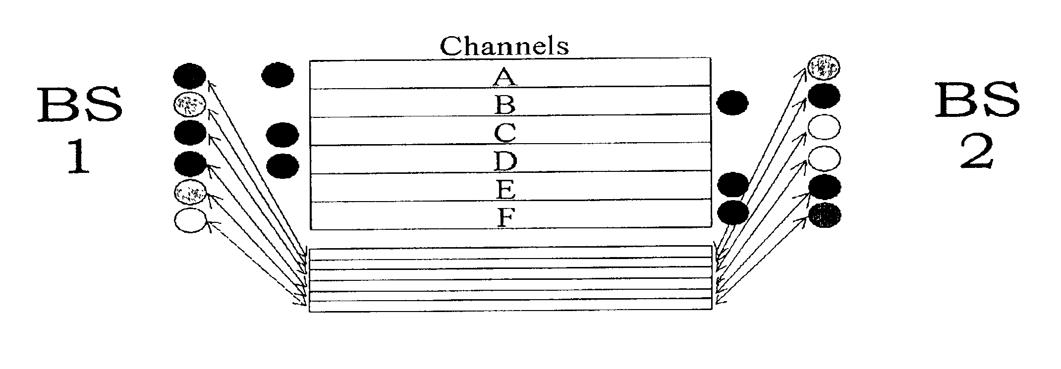
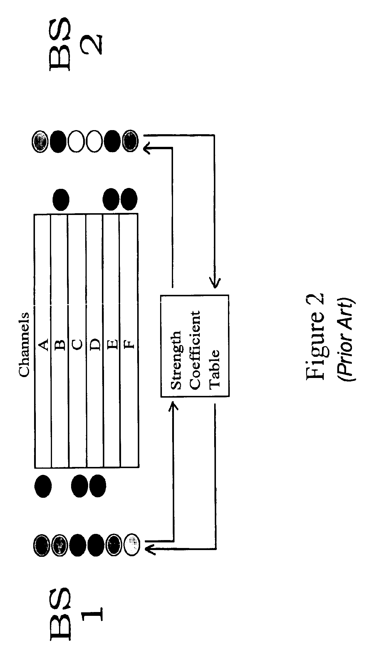
[0033]FIG. 2 shows the allocation method of the prior art system disclosed in WO99 / 56488. Each base station holds a set of preference values, indicated by the graduated shading of the six channel markers in FIG. 2. The base stations communicate these preferences to other base stations in the network, which multiply them by the relevant coefficient in the globally agreed strength coefficient table. The resulting values are used as inhibitory pressures on the preference values in the othe...


PUM


Abstract

Each base station in a network has an antenna which is connected in the conventional way to a transceiver for handling normal call traffic on one or more radio channels. In addition there is another transmitter which transmits a test signal on each of several test channels, one for each radio channel available for use by the main transceiver. The transceiver also has a receiver for detecting the test channels. The system is controlled by a timer which ensures that the transmitter and receiver do not operate at the same time. The receive times may be random, or may be co-ordinated between individual base stations. When the receiver is in operation, it will detect transmissions of the test signals from other base stations. The signal strength is measured and the result is used by a control system to determine a preference value for each channel; the stronger the signal detected, the lower the preference value. The preference value is used to control an amplifier system which controls the signal strength of each channel transmitted by the transmitter. It is also used to control the traffic transceiver by selecting which traffic channels are to be used in accordance with the preference values.

Description

[0001]This application is the U.S. national phase of international application PCT / GB00 / 04601 filed Dec. 1, 2000 which designated the U.S. This application is also related to my copending commonly assigned application Ser. No. 09 / 647,737 filed Oct. 4, 2000.BACKGROUND OF THE INVENTION[0002]1. Field of the Invention[0003]This invention relates to the allocation of channels to radio transceivers in a radio network. The described embodiments are directed to the fixed base stations of a cellular telephone network, but the invention may also find application in other networks of radio transmitters and / or receivers.[0004]2. Related Art[0005]A cellular telephone network consists of a number of fixed base station transceivers and a much larger number of mobile handsets which communicate with base stations via a radio channel. The ‘cells’ from which cellular telephone networks get their name are the coverage areas of the individual fixed radio base stations. Each operator is permitted to use ...

Claims


Application Information

Patent Timeline
IPC IPC(8): H04Q7/36H04B17/00H04W16/04
CPCH04W16/04
Inventor TATESON, RICHARD E.
Owner BRITISH TELECOMM PLC
Why Eureka
Try Eureka