Distributed cache for a wireless communication system

a wireless communication system and cache technology, applied in the field of wireless communication systems, can solve the problems of user wait experience, significant latency accumulation, and difficulty in achieving a caching rate of more than 60% based on modern internet usage patterns, and achieve the effect of improving the response time of the wireless system

Inactive Publication Date: 2005-09-06
SAMSUNG ELECTRONICS CO LTD
View PDF15 Cites 111 Cited by
  • Summary
  • Abstract
  • Description
  • Claims
  • Application Information

AI Technical Summary

Benefits of technology

[0016]In a wireless system comprising a set of limited physical coverage areas, a base station provides service over a wireless link to a plurality of users within one of the limited physical coverage areas. The base station is coupled to an Internet service provider via a backhaul. The Internet service provider is coupled to many content servers via a digital data network. Each base station has an associated cache. The cache is used to store files and objects which are frequently requested by the users within the limited physical coverage area associated with the corresponding base station. When a user sends a message comprising a request for a file or object to the base station, the base station parses the message. If the requested file or object is available from the cache, the base station forwards the file or object to the user from the cache. In this way, the request need not be sent over the backhaul or over the digital data network, thereby greatly improving the response time of the wireless system.

Problems solved by technology

The wait experienced by the user is caused by the round-trip delay from the HTTP latency as all the HTML objects which compose the hypertext markup language (HTML) file are retrieved from the Internet.
Over such great distances, even if the messages were able to travel the speed of light, a significant latency would be accumulated by the numerous round-trip delays associated with retrieving each object.
Even if the storage capacity of the cache 16 is greatly increased, it is difficult to achieve a caching rate at greater than 60% based upon modern Internet usage patterns.
Typically, the finite capacity of the wireless link as well as the limited transmission rate of the wireless link can cause additional delays in the transmission of data between the Internet service provider and the user.
The reverse process carries the objects back to the user, incurring yet additional delays.
As noted above, the cumulative delay associated with transmission of the request over the wireless link as well as the other delays associated with response to the request can become intolerably high to the end-user.

Method used


Image

  • Distributed cache for a wireless communication system
  • Distributed cache for a wireless communication system
  • Distributed cache for a wireless communication system

Examples


Embodiment Construction

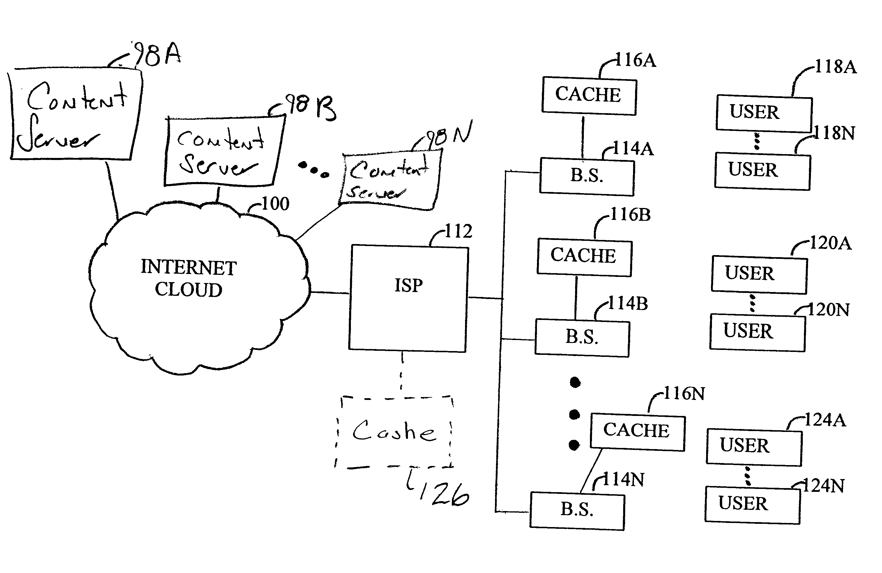
[0022]FIG. 3 is a block diagram of one embodiment of the invention. In FIG. 3, a central controller, such as an Internet service provider 112, is coupled to a digital data network, such as an Internet cloud 100 to provide connection to a group of content servers 98A-98N. In addition, the Internet service provider 112 is coupled to a series of base stations 114A-114N. Generally, the Internet service provider 112 is coupled to the series of base stations 114A-114N via a base station controller as well as a series of high capacity digital data links.

[0023]Each base station 114A-114N provides service to a corresponding physical coverage area through the use of distributed antenna sites. In one embodiment, the base stations are terrestrial base stations such as those found in a typical mobile wireless or stationary wireless telecommunications system. In another embodiment, the base stations may be co-located with one another and may provide service to distinct physical coverage areas by ...


PUM


Abstract

In a wireless system comprising a plurality of radio base station, each base station services a portion of the system. A cache is associated with each base station. The cache stores files regularly requested by the remote unit within the coverage area of the corresponding base station. When a base station receives a message from a remote unit, it parses the message to determine if the message comprises a file request. If so, the base station determines whether the file is available from the cache. If available, the base station responds to the request by forwarding the requested file from the cache. If the file is not available, the base station forwards the message to a central controller, which retrieves the file via the Internet from the appropriate content server and provides it to the base station.

Description

BACKGROUND OF THE INVENTION[0001]1. Field of the Invention[0002]The invention relates generally to wireless communication systems and, more particularly, to digital data transfer in a wireless communication system.[0003]2. Description of the Related Art[0004]Digital data communication systems are becoming more and more pervasive. For example, the Internet is commonly used to transfer digital data in the form of e-mail messages, web pages as well as audio, graphic and video information in digital format between many users and servers. FIG. 1 is a block diagram showing a typical Internet digital data system. The Internet “cloud”10 interconnects a large number of users and content servers. In order to gain access to the Internet cloud 10, an Internet service provider 12 acts as a gateway between the Internet cloud 10 and a group of users 14A-14N.[0005]In the normal course of “surfing the web”, a user accesses a series of web pages stored within a variety of content servers 8A-8N couple...

Claims


Application Information

Patent Timeline
Patent Type & Authority Patents(United States)
IPC IPC(8): G06F17/30H04L12/28G06F12/00H04W4/00H04L29/08H04W28/14H04W88/08H04W88/14
CPCG06F17/30902H04W4/00H04L67/2847H04L67/2814H04L67/2819H04L67/288H04W28/14H04W88/08H04W88/14G06F16/9574H04L67/563H04L67/564H04L67/5681
Inventor MADSEN, JAMES S.
Owner SAMSUNG ELECTRONICS CO LTD
Why Eureka
Try Eureka