VAL rotary engine

a rotary engine and cylinder head technology, applied in the direction of rotary piston engines, engine lubrication, medical atomisers, etc., to achieve the effect of less waste heat generation, less friction, and improved efficiency

Inactive Publication Date: 2005-09-13
MALINOV VALENTIN
View PDF15 Cites 18 Cited by
  • Summary
  • Abstract
  • Description
  • Claims
  • Application Information

AI Technical Summary

Benefits of technology

[0008]More particularly, the present invention relates to a VAL rotary engine having advantages of both rotary and piston engines. The rotary engine of the present invention also advantageously has a compact design.
[0011]The present invention has among its advantages that the rotor has no friction with the spherical chamber within which it operates, and that the parts which form the burning chamber are not rotating but rather swing about the center and have excellent air tight sealing and lubrication without a pressing force between the moving parts and the spherical chamber. This results in less friction, less heat, and less resistance and more power for the same amount of fuel, plus a longer life of the engine.
[0013]Further, with the present invention, because the engine is very compact and the distance between the main shaft and the valves is small, it is advantageously possible to open the valves in a simple way by using a shaft driving cam sleeve with two cams only, one for each working chamber. The cams serve to push up the lifting rods which actuate the valves. The expansion of the lifting rods will be compensated with the hydraulic compensator, that is, the lifting rods can be positioned in the exact necessary locations around the cam sleeve.
[0016]2. There is excellent lubrication by the splashing and the oil pump.
[0019]5. Less friction, which means less waste heat generation, better efficiency, and better reliability as compared with the prior art piston engines.

Problems solved by technology

From the foregoing, it is seen that it is a problem in the art to provide a device meeting the above requirements.

Method used


Image

  • VAL rotary engine
  • VAL rotary engine
  • VAL rotary engine

Examples


Embodiment Construction

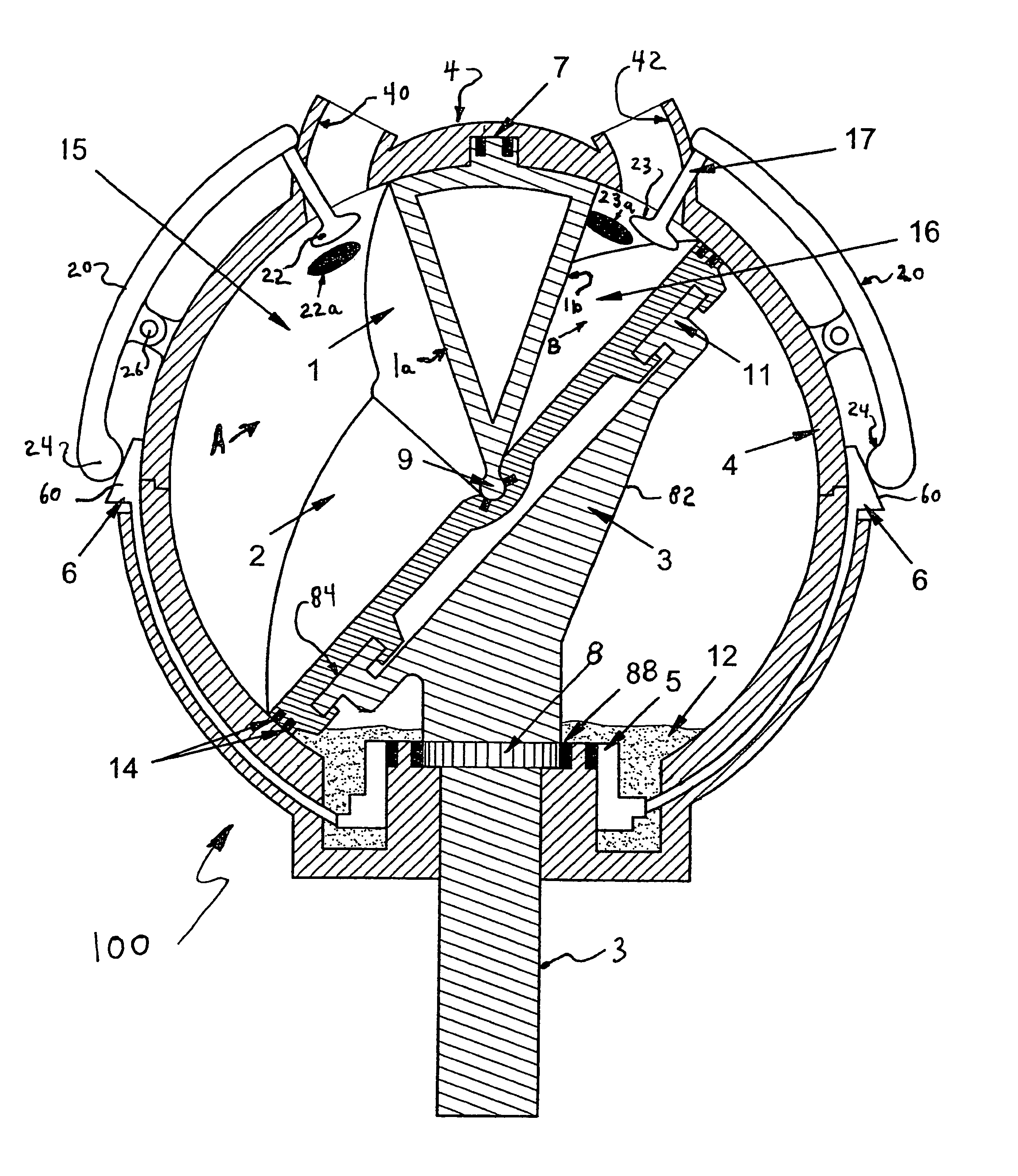
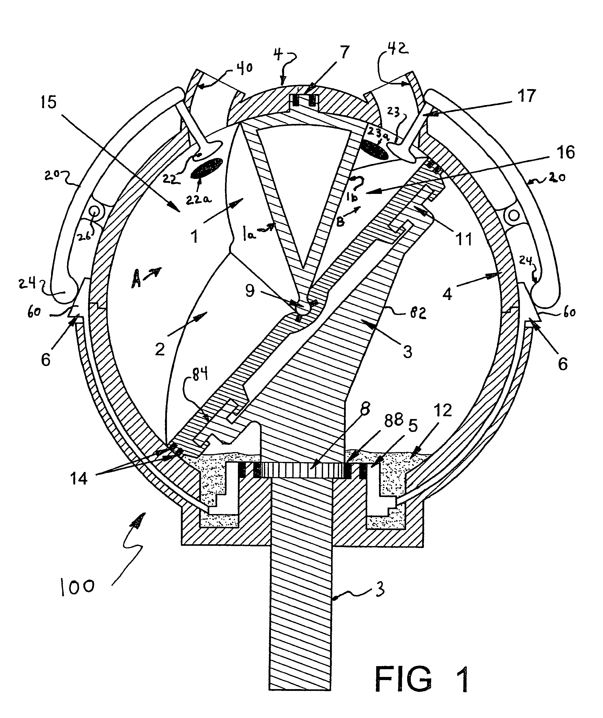
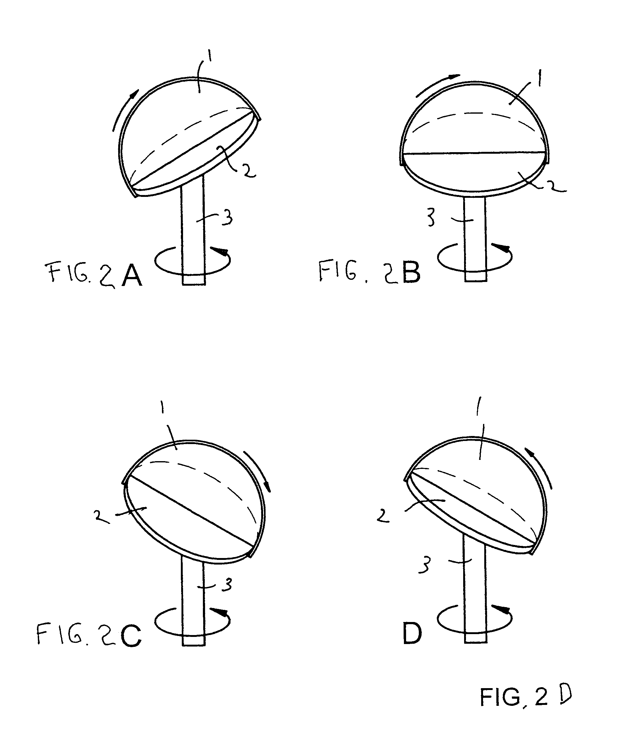
[0043]FIG. 1 shows a schematic, side sectional view of a rotary engine 100 according to the present invention. The rotary engine 100 includes a spherical member 4 housing a first baffle member 1 and a second baffle member 2. The spherical member 4 also houses a rotor 3 which is connected to a shaft extending beyond the spherical member 4. The spherical member 4 has four ports, two in each chamber. As viewed in FIG. 1, there is four ports 17 which include openings 40, 42, 22a, and 23a. Such ports are conventional in internal combustions engines and no further description is necessary inasmuch as the skilled artisan will understand how to place and operate such ports. The valves 22 and 23 are respectively disposed so as to open and close openings 22a and 23a.

[0044]The first baffle member 1 and the second baffle member 2 together divide the interior of the spherical member 4 into a first combustion chamber 15 and a second combustion chamber 16, as seen in FIG. 1. The first baffle memb...


PUM


Abstract

A rotary engine has a spherical enclosure serving as a combustion chamber, a first baffle inside the combustion chamber slideable along a groove formed in the spherical enclosure, and a second baffle disposed in the combustion chamber which is in sealing engagement with the internal spherical surface of the combustion chamber. The second baffle is carried by a rotatable shaft, the shaft extending into the spherical combustion chamber. The first baffle rests against the second baffle, and separates the interior of the combustion chamber into a first part and a second part. A first valve in a first opening is disposed to communicate with the first part of the combustion chamber, and a second valve in a second opening is disposed to communicate with the second part of the combustion chamber.

Description

FIELD OF THE INVENTION[0001]The present invention relates to a rotary internal combustion engine.BACKGROUND OF THE INVENTION[0002]Internal combustion engines are known in the art. Further, rotary internal combustion engines are known in the art.[0003]There are disadvantages of the existing rotary internal combustion engines as compared with existing four stroke piston engines. For example, rotary internal combustion engines can not match the reliability of piston engines. Problems of existing rotary internal combustion engines may include poor lubrication, overheating, excessive friction between the rotor and cylinder, and insufficient number of cycles.[0004]Although well known for its reliability, there are well known disadvantages of existing four stroke piston internal combustion engines. For example, major disadvantages of piston engines include the necessity to accelerate and stop the piston and the connection rod four times in each single working cycle for a cylinder. This rep...

Claims


Application Information

Patent Timeline
Patent Type & Authority Patents(United States)
IPC IPC(8): A61M11/00F01C3/00F02B33/00F02B53/00F01C9/00F01C11/00F02B53/06F02B55/14
CPCF01C9/005F01C11/002F02B53/06F02B55/14F02B2730/02
Inventor MALINOV, VALENTIN
Owner MALINOV VALENTIN
Why Eureka
Try Eureka