
Brake system having boosted hydraulic accumulator

a technology of hydraulic accumulator and brake system, which is applied in the direction of brake cylinders, mechanical control devices, instruments, etc., can solve the problems of requiring a large force for mechanical brake systems to release brake pedals, affecting the service life of the system, and requiring high strength structural components to withstand continued service, so as to boost the magnitude of energy stored

Inactive Publication Date: 2005-09-13
TEXTRON INNOVATIONS
View PDF26 Cites 7 Cited by
  • Summary
  • Abstract
  • Description
  • Claims
  • Application Information

AI Technical Summary

Benefits of technology

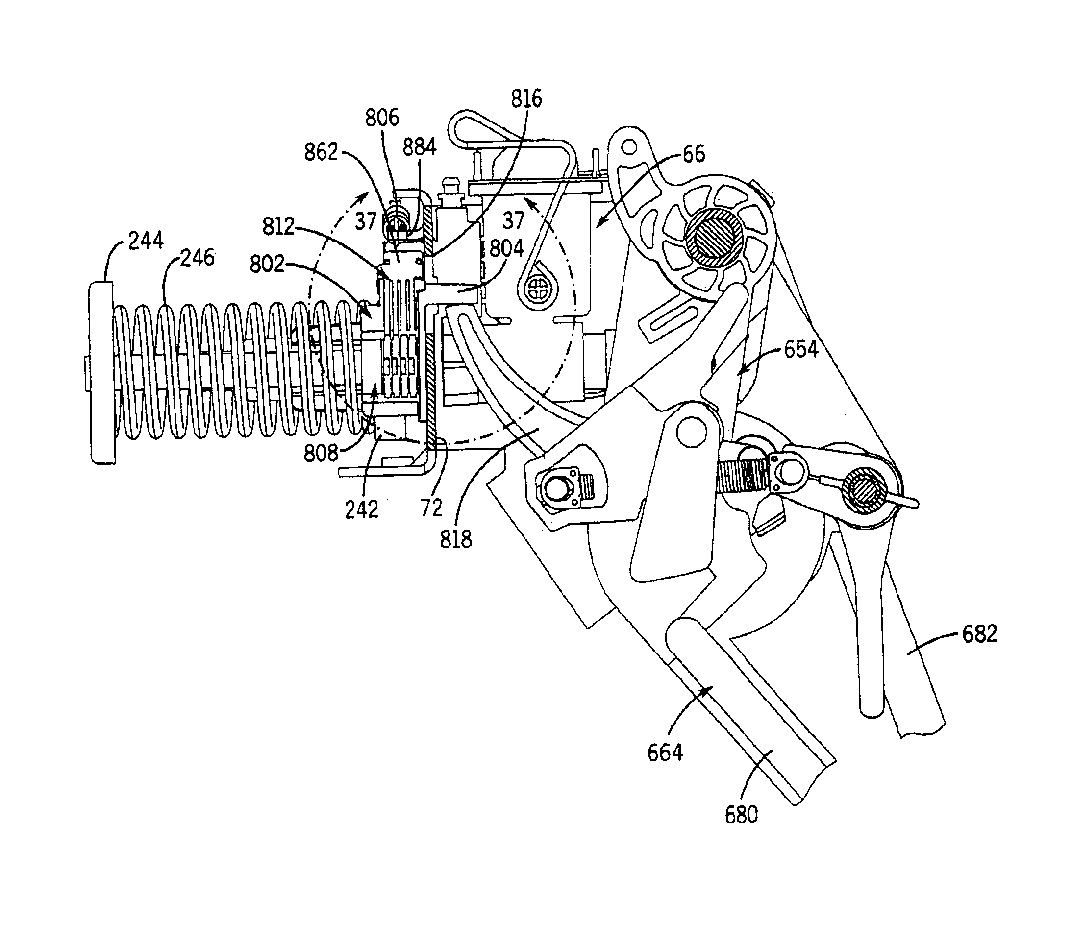
The invention provides an effective accumulator booster for a vehicular brake system that includes a master cylinder, a hydraulically actuated vehicle brake, a master cylinder, an accumulator, and a booster. The booster automatically operates during a braking cycle to hold the brake in the engaged position, without requiring manual deactivation. The accumulator stores energy during the braking cycle and uses it to assist in holding the brake in the engaged position. The booster interacts with the accumulator such that the spring is compressed more during the energy storage phase of the second braking cycle than during the first braking cycle. The booster may be retrofit into existing systems and includes an indexing arm, an actuator arm, and a variable thickness spacer. The method of boosting the energy storage capacity of the accumulator involves sequentially applying the brakes and latching them in the applied condition, with the accumulator storing energy during the braking cycle. The accumulator stores at least the same magnitude of energy during each of the N+1st through Mth braking cycles, where N and M are both greater than 1.

Problems solved by technology

While these mechanical systems are acceptable for many applications, they exhibit marked disadvantages when compared to hydraulic brake systems of the type employed by most heavy-duty vehicles.
For instance, due at least in part to the fact that mechanical brake systems exhibit substantial hysterisis when compared to hydraulic systems, the operator of the typical mechanical brake system must impose a substantial force to the primary brake pedal to effect braking of the typical mechanical brake system, and a similar force is required to actuate an associated brake locking arrangement.
These mechanical brake systems also require a relatively large force to release the brake pedal from its locked position.
A further disadvantage resulting from the relatively large operating forces required to actuate and / or release mechanical brake systems is the need for high strength structural components to withstand continued service without associated maintenance problems.
However, brake release in systems of this type typically requires that the accelerator pedal must be depressed through a substantial stroke and / or against substantial resistance to accelerator pedal movement.
As a result, the operator must impart so much force to release the brakes that the accelerator pedal is driven through a substantial percentage of its service stroke before the brakes are released, resulting in near-instantaneous and relatively rapid vehicle acceleration upon brake release.
The vehicle therefore jerks forward at substantial operator discomfort and at the risk of loss of vehicle control.
At least the lightest settings of some of these multipoint latching systems might not produce a strong enough holding force to assure adequate braking on steep slopes.
However, single latching point systems usually exhibit a pronounced snapback effect and high efforts to set on the brake pedal (produced by the rapid release of accumulated energy from a fully-engaged brake) that produces an undesirable, relatively loud noise and system hammering and that produces substantial wear and tear on the brake pedal and related components.
In some systems, this snap back can be so severe as to risk operator injury.
Another problem associated with systems having either single point latching or multipoint latching is that the latching components of these systems contact one another at several different points in both the latching and unlatching operations, producing several distinct audible clicks that may confuse the operator into believing that the brakes are locked when they are not and / or that the brakes have been released when they are still locked.
Yet another problem associated with known hydraulic combined service brake / park and hold brake systems is that they lack any structure that ensures pressure retention in the brakes in the event of gradual relatively minor pressure reduction in the system.
Absent some mechanism to make up for the holding energy lost due to creep, the brake holding forces may decrease over time to a level that that risks unintended partial brake release and consequent unwanted vehicle movement.
A problem associated with accumulator-equipped hydraulic park and hold braking systems is that the accumulator of the system may not store sufficient energy to make up for higher magnitude fluid pressure losses resulting, e.g., from severe temperature drops.
However, an accumulator may be incapable of storing sufficient energy to compensate for larger pressure changes resulting, e.g., from severe temperature drops.
For instance, the brakes of a golf car or similar vehicle may be latched on a relatively warm autumn day, and the vehicle may then be stored through the winter, where it is subject to a temperature drop of 70° F. The braking system may suffer such a severe volumetric change and resultant pressure drop as a result of this temperature drop that the system's accumulator cannot store enough energy to pressurize the system sufficiently to maintain the brakes in their engaged condition.
The “creep” that otherwise would be avoided through the incorporation of an accumulator into the system may therefore still present a problem.
This pressure loss and resultant strain on the accumulator are especially dramatic in relatively poorly bled systems having relatively large quantities of air in the hydraulic fluid.
However, energizing the oversized accumulator would noticeably increase the effort required to latch the brakes, particularly if the accumulator were manually energized by actuation of the system's brake pedal.
Space constraints also prohibit accumulator oversizing in some applications.
Specifically, when an operator of this type of system desires to park the vehicle for a long term, he or she would have to depress the brake pedal while simultaneously manually actuating the booster, thus blocking the accumulator from returning to its fully released or “home” position.

Method used


Image

  • Brake system having boosted hydraulic accumulator
  • Brake system having boosted hydraulic accumulator
  • Brake system having boosted hydraulic accumulator

Examples


Embodiment Construction

1. Resume

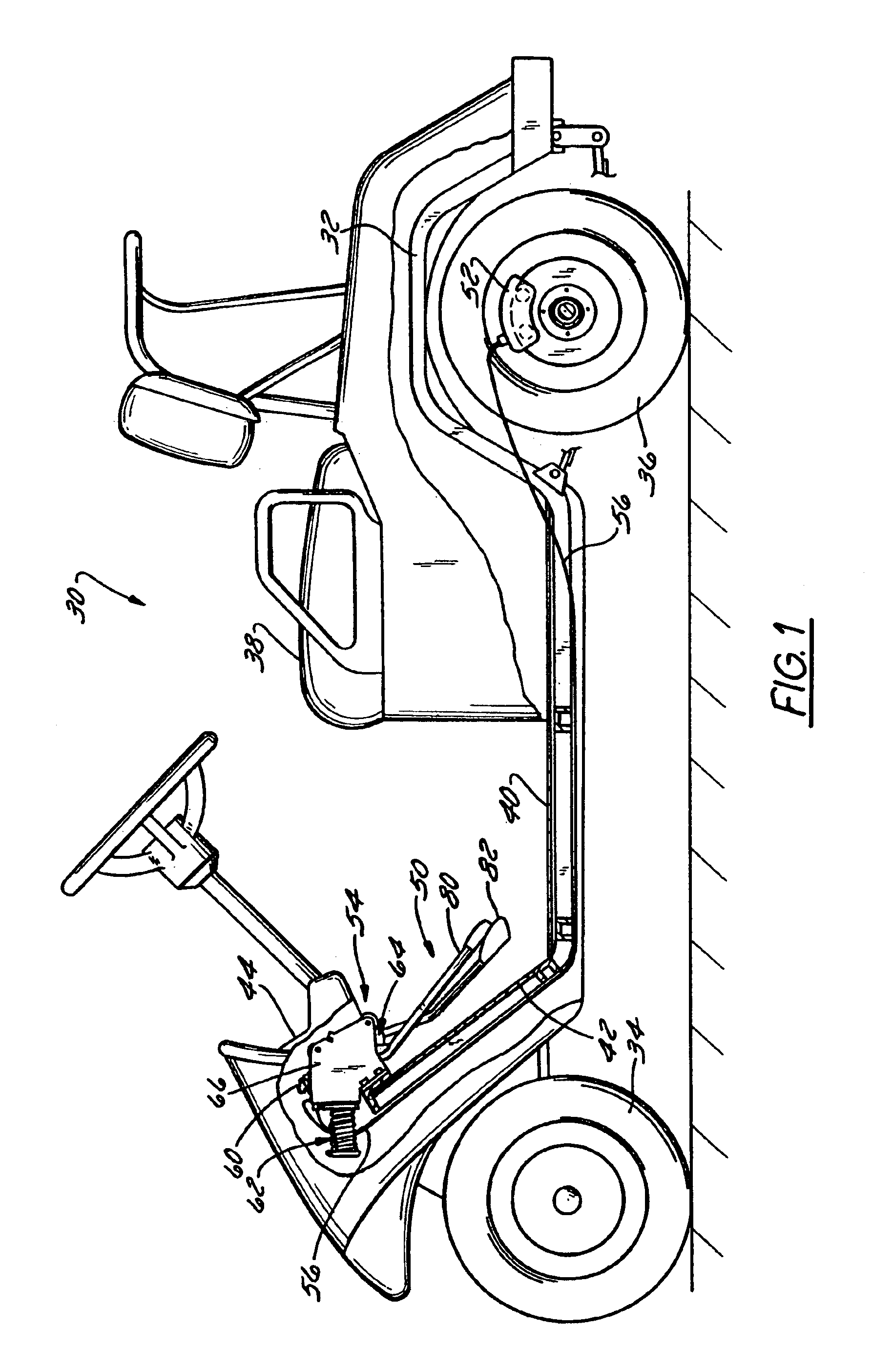
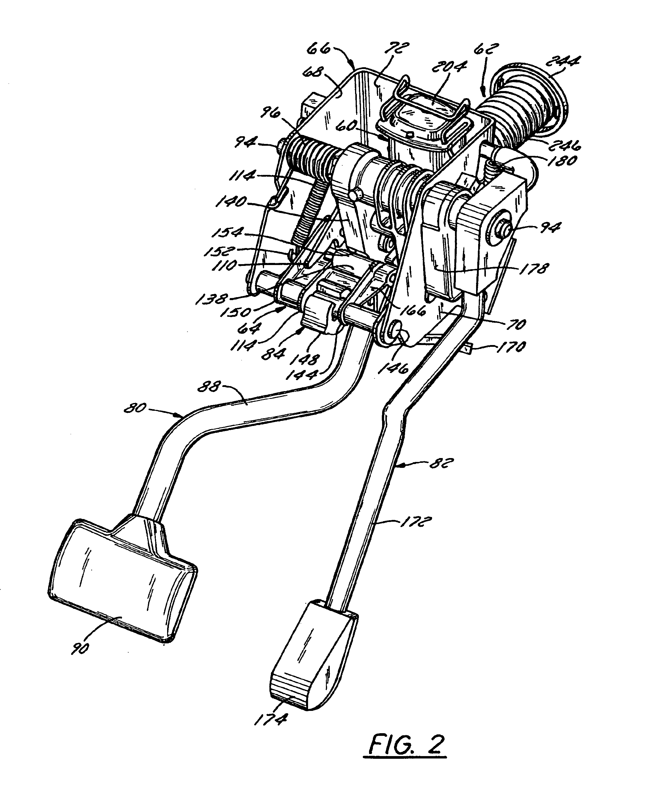
[0060]Pursuant to a preferred embodiment of the invention, a hydraulic brake system is provided for a vehicle such as a golf car or the like that uses the same brakes and same brake pedal for both service braking and park and hold braking. The system additionally includes a hydraulic accumulator that stores much of the energy generated upon brake pedal depression. The stored energy can be used to maintain the brakes in their fully engaged state and to help return an applied brake pedal to its released position, in which case return fluid flow to the master cylinder is damped to avoid undesirable severe kickback of the brake pedal. A booster is provided to automatically boost the energy storage capacity of the accumulator during normal brake and hold cycles in order to provide sufficient energy accumulation to compensate for relatively severe pressure drops occurring, e.g., during prolonged periods of storage at decreasing temperatures.

2. System Overview

[0061]The invention, ...


PUM


Abstract

A hydraulic brake system includes a hydraulic accumulator that stores much of the energy generated upon brake pedal depression. The stored energy can be used to maintain the brakes in their fully engaged state and to help return an applied brake pedal to its released position, in which case return fluid flow to the master cylinder is damped to avoid undesirable severe kickback of the brake pedal. A booster is provided to automatically boost the energy storage capacity of the accumulator during normal brake and hold cycles in order to provide sufficient energy accumulation to compensate for relatively severe pressure drops occurring, e.g., during prolonged periods of storage at extremely low temperatures. The booster may comprise an indexing arm that is acted upon by the system's brake pedal to selectively move a variable thickness spacer on the indexing arm into and out of engagement with the accumulator.

Description

CROSS REFERENCE TO RELATED APPLICATIONS[0001]This application is a divisional of U.S. patent application Ser. No. 10 / 308,970, filed Dec. 3, 2002 U.S. Pat. No. 6,796,407, which is a continuation-in-part of U.S. patent application Ser. No. 09 / 914,867, filed Mar. 13, 2002, which is a national phase of PCT Application Ser. No. PCT / US00 / 05427, filed Mar. 2, 2000, which claims the benefit of priority of U.S. Provisional Application Ser. No. 60 / 122,405, filed Mar. 2, 1999, the entire contents of each of which are hereby expressly incorporated by reference into the present application.BACKGROUND OF THE INVENTION[0002]1. Field of the Invention[0003]The invention relates to a hydraulic combined service brake / park and hold brake system having an accumulator and a booster that automatically boosts the energy storage capacity of the accumulator during the first brake braking cycle(s) to compensate, e.g., for volumetric changes in the system that might take place during prolonged periods of non-u...

Claims


Application Information

Patent Timeline
Patent Type & Authority Patents(United States)
IPC IPC(8): B60T11/18B60T11/22B60T1/06B60T17/22B60T17/16B60T11/236B60T1/00B60T11/10B60T11/16B60T17/00B60T7/04B60T17/18F16D55/228F16D55/22F16D55/00
CPCB60T1/065B60T11/103B60T11/105B60T11/165B60T11/18B60T11/22B60T11/236B60T17/16B60T17/222F16D55/228B60T7/045Y10T74/20528F16D2055/002F16D2055/007F16D2055/0091B60T7/06B60T13/04B60T13/22B60T13/588
Inventor BUCKLEY, JAMES A.WALTERMAN, SCOTT A.BIGSBY, BRIAN
Owner TEXTRON INNOVATIONS
Learn More