Disposable knee mold

a knee joint and mold technology, applied in the field of implants, can solve the problems of increasing surgical time, soft tissue damage, and the need to reconstruct or replace the knee join

Inactive Publication Date: 2005-09-13
ORTHO DEV CORP
View PDF18 Cites 193 Cited by
  • Summary
  • Abstract
  • Description
  • Claims
  • Application Information

AI Technical Summary

Problems solved by technology

However, when the knee joint becomes diseased, damaged or is otherwise unable to withstand the forces required of that joint, it may become necessary to reconstruct or replace the knee joint.
However, there are many problems associated with such methods and designs, namely increased surgical time due to the preparation and formation time needed for creating the implant.
Particular problems associated with the block or spacer method include completely immobilizing the knee in an extended position, after surgery, for the entire 6-8 week period, which in turn leads to soft tissue damage and further complicates the revision surgery.
This device is characterized by several disadvantages, including the need for many different sized molds to accommodate the differences in size of patients tibias and femurs, the need for multiple pieces that must be joined together and the need to use the mold outside the patient's knee joint such that the implant must first be formed and then attached to the tibia or femur in two separate steps.
However, this technique is disadvantageous because it requires the surgeon to conform the foil to the bone and to further form the bone cement into the shape of a femoral or tibial component.
In this setting, another disadvantage in the aluminum foil is its ductility.
The foil is unable to spring back into its original shape or position making it very difficult to work with and to maintain its shape as the cement is poured into the mold and while the cement is allowed to cure.
However, such attempts have proven to be unsuccessful because the rigid, non-resilient nature of the materials used, such as metal or a metal alloy.
However, there are several disadvantages associated with non-resilient molds, for example, non-resilient molds do not have the requisite flexibility to be used in situ, as it is difficult to remove the implant from the mold and there is no flexibility for the mold to be conformed to various anatomical differences in the bones.
It is noteworthy that none of the prior art, known to applicants, provides an elastic mold capable of being attached in situ that further provides for a one piece mold capable of attaching to various sized bone components.

Method used


Image

  • Disposable knee mold
  • Disposable knee mold
  • Disposable knee mold

Examples


Embodiment Construction

[0025]For the purposes of promoting an understanding of the principles in accordance with the invention, reference will now be made to the embodiments illustrated in the drawings and specific language will be used to describe the same. It will nevertheless be understood that no limitation of the scope of the invention is thereby intended. Any alterations and further modifications of the inventive features illustrated herein, and any additional applications of the principles of the invention as illustrated herein, which would normally occur to one skilled in the relevant art and having possession of this disclosure, are to be considered within the scope of the invention claimed.

[0026]Before the present device and methods for surgically positioning the disposable knee mold, in situ, are disclosed and described, it is to be understood that this invention is not limited to the particular configurations, process steps, and materials disclosed herein as such configurations, process steps,...


PUM

PropertyMeasurementUnit
elasticaaaaaaaaaa
thicknessaaaaaaaaaa
biocompatibleaaaaaaaaaa

Abstract

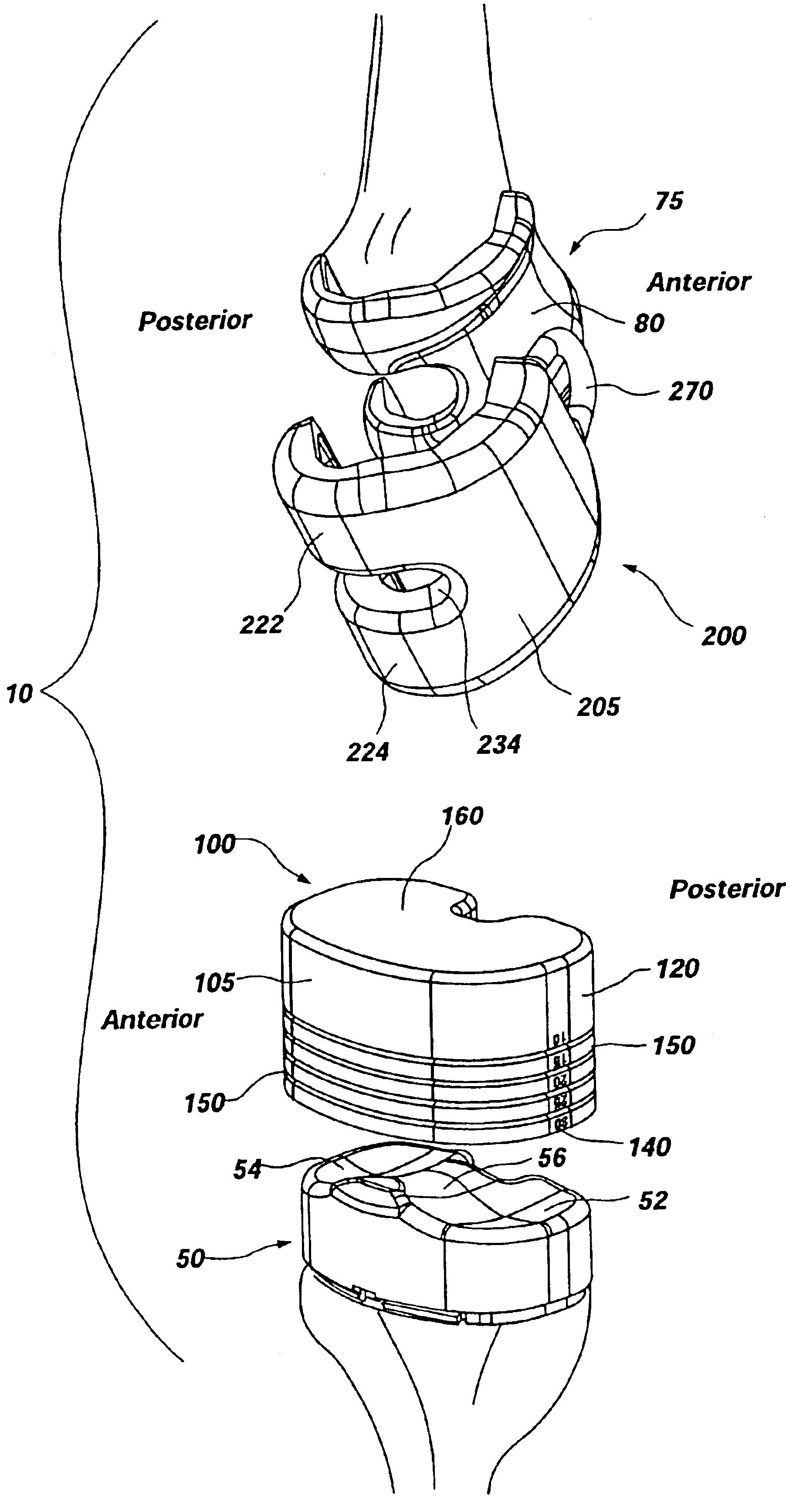
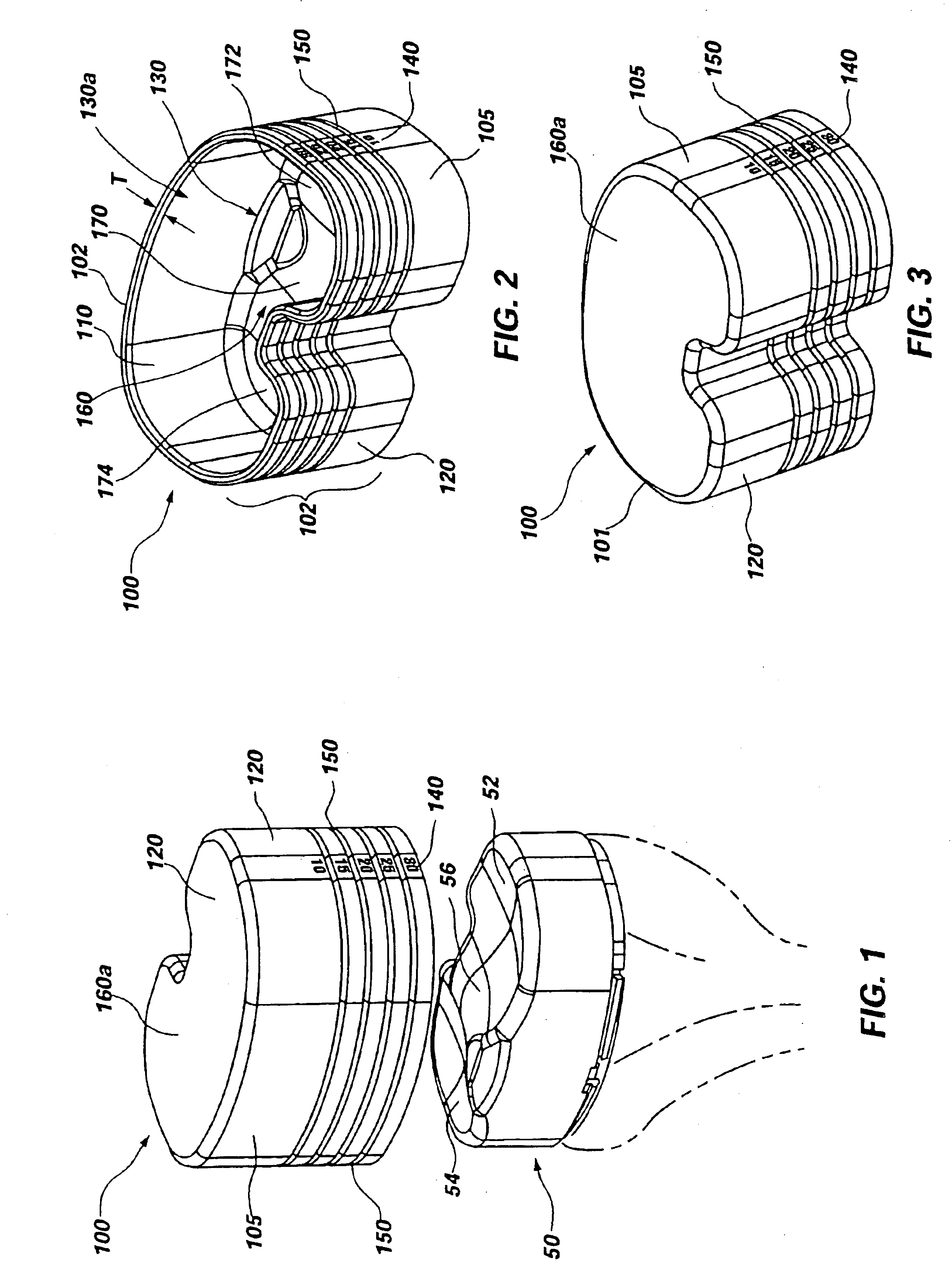
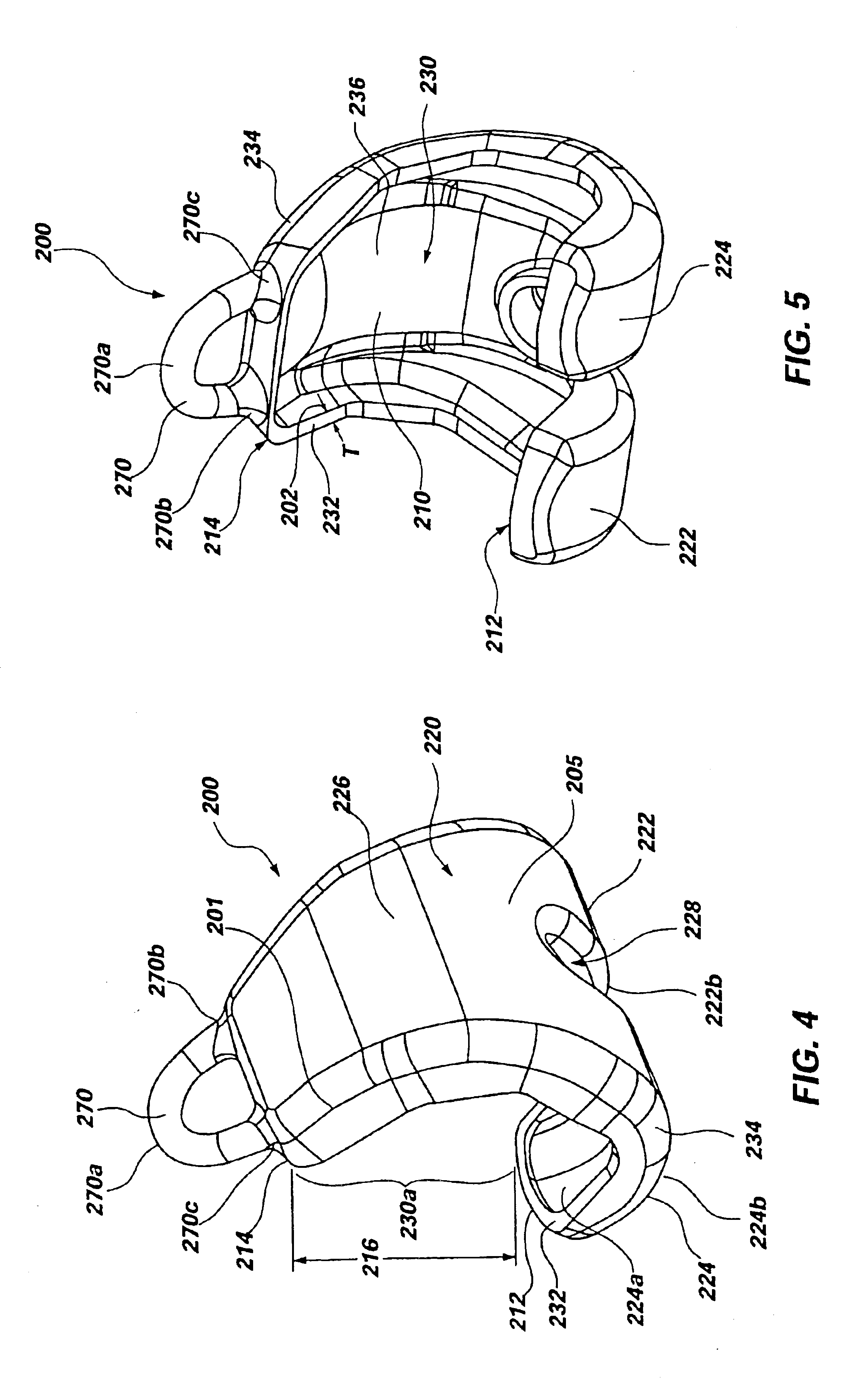
An orthopedic implant device and method is disclosed. Specifically, a knee mold system is disclosed, including elastic tibial and femoral molds, each of which may be configured and dimensioned as a unitary mold for in situ placement during a surgical procedure. Each mold may be manufactured from an elastic material that may be disposable. The tibial mold may further comprise a sidewall forming a cavity, markings for relative depth measurement, and depth rings for use as a guide for scoring, cutting, and / or trimming and tearing away an excess portion of the tibial mold. The femoral mold may further comprise a sidewall defining a cavity, two legs extending from a body of the femoral mold for forming the artificial condyles, and an eyelet for aiding in placement and removal of the femoral mold. The resulting prosthetic tibial and femoral components may form an articulation surface that mimics, at least in part, the natural articulation surface of the knee.

Description

CROSS-REFERENCE TO RELATED APPLICATIONS[0001]This application claims the benefit of U.S. Provisional Application No. 60 / 364,061, filed Mar. 13, 2002, which is hereby incorporated by reference herein in its entirety, including but not limited to those portions that specifically appear hereinafter, the incorporation by reference being made with the following exception: In the event that any portion of the above-referenced provisional application is inconsistent with this application, this application supercedes said portion of said above-referenced provisional application.STATEMENT REGARDING FEDERALLY SPONSORED RESEARCH OR DEVELOPMENT[0002]Not Applicable.BACKGROUND OF THE INVENTION[0003]1. The Field of the Invention[0004]The present invention relates generally to implants for use in orthopedic surgery, and more particularly, but not necessarily entirely, to molds for forming temporary orthopedic implants in the knee.[0005]2. Description of Related Art[0006]The anatomy of the knee is p...

Claims


Application Information

Patent Timeline
Patent Type & Authority Patents(United States)
IPC IPC(8): A61F2/30A61F2/38B29C33/40B29C39/10A61F2/00
CPCA61F2/30942A61F2/38B29C33/405B29C39/10A61F2002/30133A61F2002/30616A61F2002/30957B29C43/36B29C2043/3652B29K2995/0056B29L2031/7532A61F2002/30672Y10S623/901Y10S264/30Y10S425/044
Inventor ENSIGN, MICHAEL D.LOWE, MATTHEW M.MARIANI, E. MARCBOURNE, MICHAEL H.
Owner ORTHO DEV CORP
Why Eureka
Try Eureka