
Dental handpiece comprising torque-limiting means

a technology of torque-limiting means and handpieces, which is applied in the field of handpieces, can solve the problems of reducing the overall volume of the overall volume of the overall volume of the overall volume of the overall reducing the overall volume of the overall volume, and reducing the risk of root canal damag

Inactive Publication Date: 2005-09-13
ANTHOGYR SAS
View PDF10 Cites 14 Cited by
  • Summary
  • Abstract
  • Description
  • Claims
  • Application Information

AI Technical Summary

Benefits of technology

"The present invention provides a dental handpiece that can automatically limit the drive torque of a rotary dental tool without increasing its overall size or requiring expensive mechanical means. The handpiece can adjust the maximum torque limit to match different tools, ensuring efficient operation and reproducible results. The handpiece includes a torque limiter means and means for adjusting the maximum torque limit. The torque limiter means include a male coupling portion and a female coupling portion with a coaxial annular surface overlapping each other, and at least one rotary coupling member mounted to slide radially in a transverse passage. The handpiece can also include calibration means and position adjustment means for the male coupling portion. The technical effects of the invention include improved precision and reproducibility of the maximum torque limit, reduced risk of damage to the tool, and efficient operation of the dental tool."

Problems solved by technology

There is then the risk of damage to the root canal and, more importantly, of breaking the rasp.
Obviously, removing a broken section of rasp wedged into the very narrow root canal is a difficult operation.
It is often impossible to remove this broken section and therefore impossible to complete the treatment of the root canal.
A solution of this kind is costly, on the one hand because the torque limiter is itself costly and on the other hand because it cannot be fitted to existing motors that the dentist has already acquired.
The maximum torque transmitted cannot be adjusted, which makes the handpiece unsuitable for use in endodontal work, because it is usually necessary to employ several tools in succession having different diameters and therefore different permissible maximum torques.
This results in progressive wear of the plates in service.

Method used


Image

  • Dental handpiece comprising torque-limiting means
  • Dental handpiece comprising torque-limiting means
  • Dental handpiece comprising torque-limiting means

Examples


Embodiment Construction

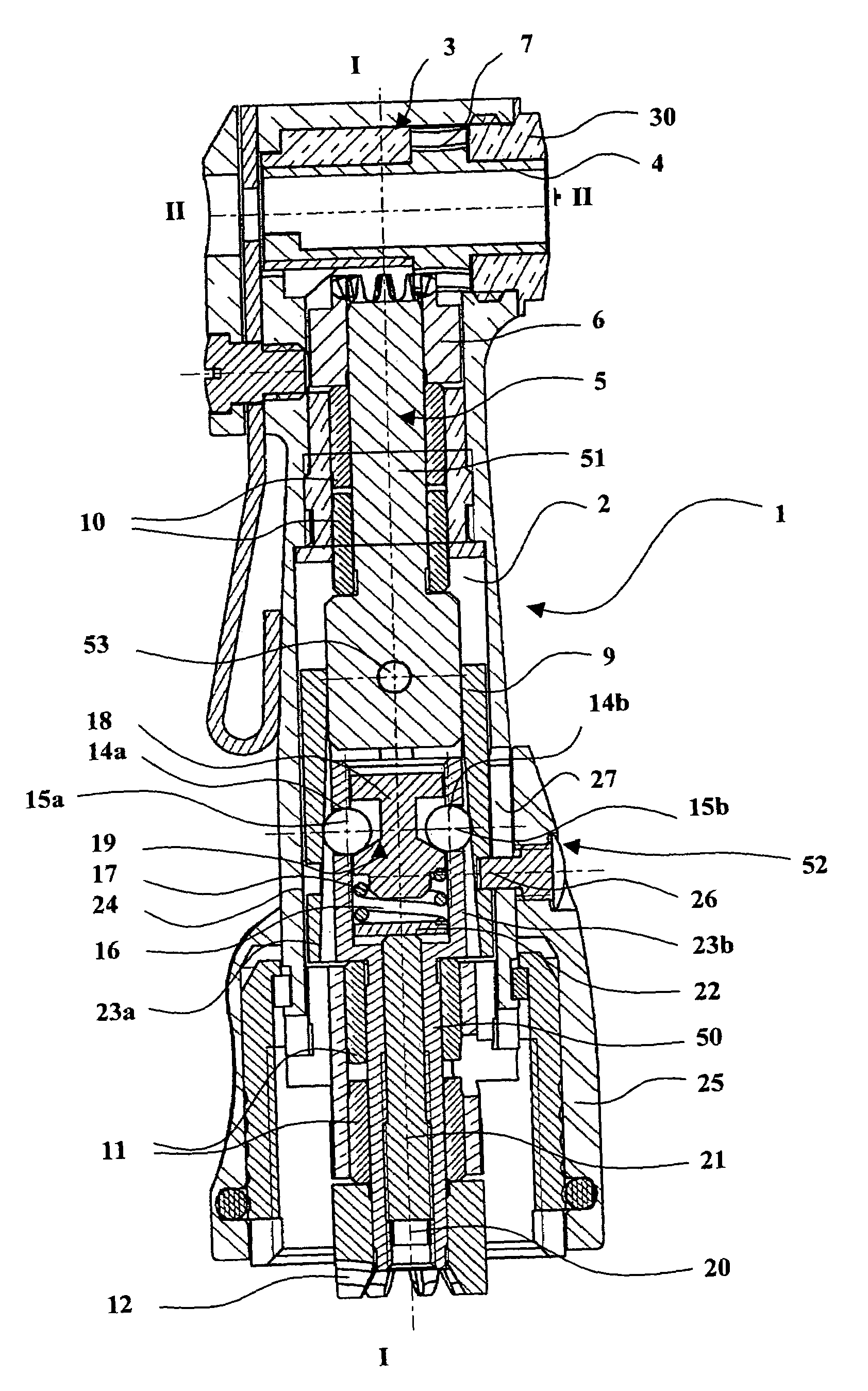
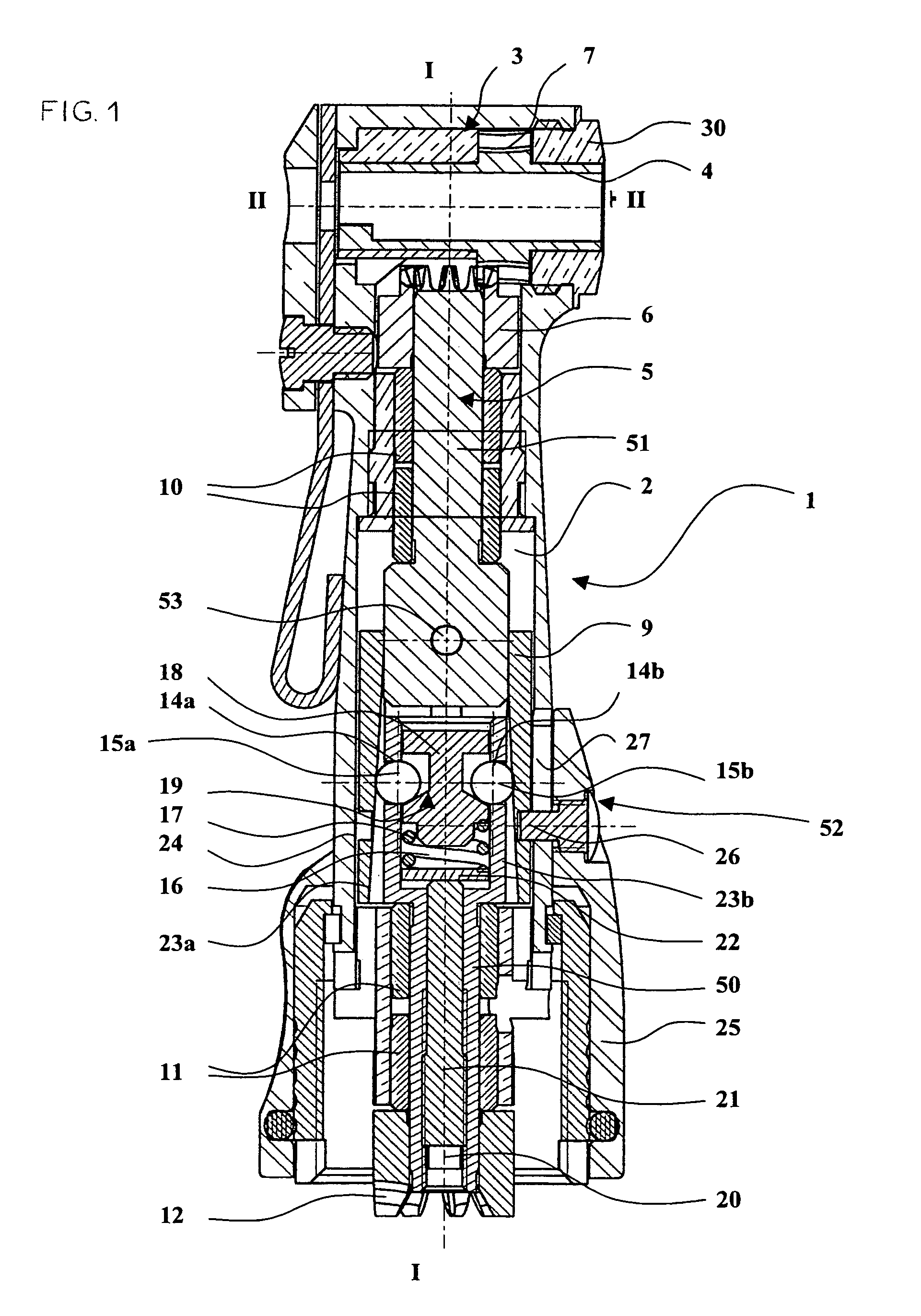
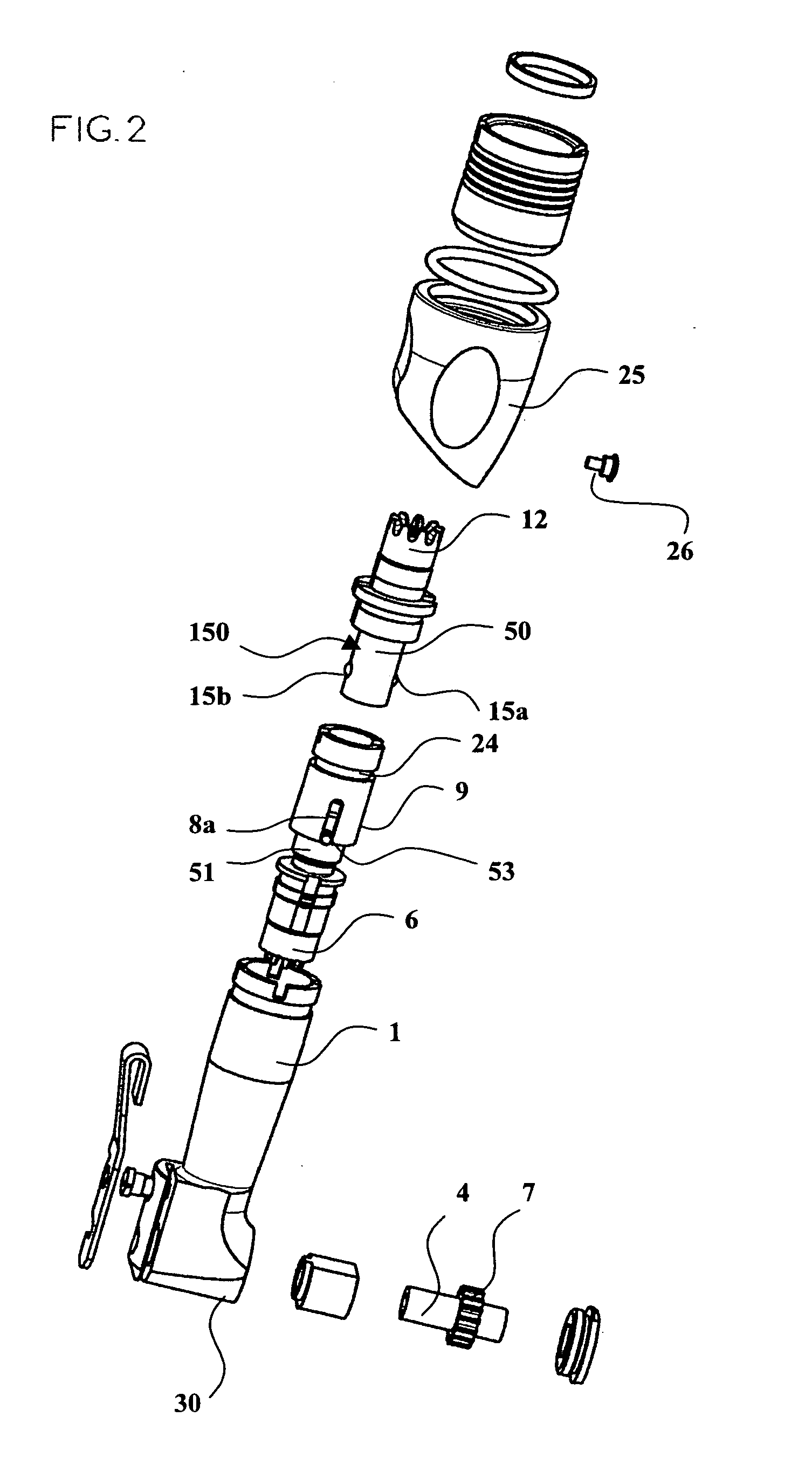
[0056]In all the embodiments shown in the figures, a dental handpiece according to the invention includes a handpiece neck 1 in which there is a longitudinal bore 2 communicating with a transverse bore 3 of a handpiece head 30 which is fastened to it. A transverse tool-carrier shaft 4 is mounted in the transverse bore 3 of the handpiece head 30 to rotate about the transverse axis II—II, and includes a tool-holder for separably fixing a tool to the tool-carrier shaft 4.

[0057]A drive shaft 5 is mounted in the longitudinal bore 2 to rotate about the longitudinal axis I—I. The drive shaft 5 is made up of a primary shaft 50 and a secondary shaft 51 which are coaxial and coupled together in series by means 52 for limiting the maximum torque that can be transmitted. The secondary shaft 51 is guided by bearings 10, and has at its distal end, near the tool, a gear 6 which cooperates with peripheral teeth 7 on the tool-carrier shaft 4. Between the adjacent ends of the primary shaft 50 and sec...


PUM


Abstract

A dental handpiece is provided including a neck wherein balls are guided in transverse channels of an input shaft and are radially spaced apart by a support piece including a tapered part thrust by a spring. A linking ring is mounted on the end of the input shaft and includes internal longitudinal grooves circular in cross-section and of variable depth along the longitudinal direction. The linking ring is mounted sliding and locked in rotation on an output shaft. Under the action of a resisting torque applied by the tool to the output shaft greater than a predetermined threshold, the linking balls are subjected to a reaction from the internal grooves of the linking ring which tends to bring them closer together, countering the spring. The balls are then released, producing a disengagement which limits the transmitted torque and prevents the tool engaged in the tool-bearing shaft from breaking.

Description

[0001]This application is the U.S. national phase application of PCT International Application No. PCT / FR00 / 02723 filed 2 Oct. 2000.TECHNICAL FIELD OF THE INVENTION[0002]The present invention concerns handpieces, used in dentistry, on which a rotary dental tool can be mounted and driven in unidirectional rotation about its axis.[0003]Small rotary tools are often used to work in the mouth, for example rasps for working on root canals, which take the form of a fine rod holded oblique or perpendicular to the general direction of entry into the mouth. A swan-neck dental handpiece is generally used for this purpose, which the dentist can couple mechanically to an electric or pneumatic motor. Swan-neck dental handpieces have a main body coaxial with the rotation axis of the drive motor and in which there is a longitudinal bore, followed by a portion called the neck at an angle of the order of 15° to 30° to the body and in which there is also a longitudinal bore, and finally a portion call...

Claims


Application Information

Patent Timeline
Patent Type & Authority Patents(United States)
IPC IPC(8): A61C1/18A61C1/08A61C1/02F16D7/10F16H35/10
CPCA61C1/185A61C1/186
Inventor RICHARD, HERVE
Owner ANTHOGYR SAS
Learn More