Prosthesis

a technology for prostheses and acetabular joints, applied in the field of prosthesis, can solve the problems of affecting the life expectancy of prostheses, fatigue fracture and wear, and breakage of either the bone or the cement used to bond the prosthesis to the bone, and achieve the effect of facilitating and promoting bone ingrowth into the outer portion, and being more rigid

Inactive Publication Date: 2005-09-13
FINSBURY DEV
View PDF8 Cites 23 Cited by
  • Summary
  • Abstract
  • Description
  • Claims
  • Application Information

AI Technical Summary

Benefits of technology

[0015]The acetabular prosthesis of the invention is designed for implantation into a surgically prepared cavity in the hip of a patient. Since the human pelvis comprises a structure of three bones with considerable flexibility, a normal pelvis can accommodate reasonable stresses and deformation imposed, for example, by vigorous exercise or by leaping off a fence, by relative movement between these bones. Moreover the pelvic bones themselves can flex considerably to accommodate such loading. On the other hand a conventional acetabular prosthesis, which is typically made of titanium, a titanium alloy or cobalt-chrome, is much more rigid than the surrounding bone in which it is implanted. Normally such conventional acetabular prostheses will be held in place by engagement of exterior screw threads positioned substantially equatorially around the periphery of the prosthesis with the patient's bone, by means of screws, by means of bone cement, or by a combination of these. Because a conventional implant is much more rigid than the patient's bone, there is a considerable risk of damage occurring when a patient's hip in which the acetabular prosthesis has been implanted is subjected to stress. This damage can manifest itself in damage to the pelvic bones, in fracture of the bond between the prosthesis and the surrounding bone, or in progressive migration of the implant leading to failure. If the damage is sufficiently severe, then a revision operation may be necessary.
[0016]The acetabular prosthesis of the present invention may be secured in place by use of external screw threads, by use of screws, by use of bone cement, or by a combination of two or more of these methods of securement; alternatively, or in addition to one or more of these methods of securement, the substantially convex outer surface of the outer portion of the acetabular prosthesis of the present invention may be formed at least in part as a porous surface or provided with an adhesively bonded bone promotion layer, such as a layer of hydroxyapatite, so as to facilitate and promote bone ingrowth into the outer portion of the acetabular prosthesis.
[0017]Preferably the outer portion of the acetabular prosthesis of the invention is relatively flexible. Desirably its flexibility should match as closely as possible that of a typical human pelvic bone as a complete structure. In this way it can, after implantation in a patient, accommodate a localised increase in stress by absorbing stress applied to the hip joint as the patient undertakes his or her normal activities with a significantly reduced risk of any fracture of the bone or of the prosthesis becoming dislodged due, for example, to rupture of any cement bond by means of which the implant is retained in the bone.

Problems solved by technology

It is well known that a major factor influencing the life expectancy of a prosthetic implant is fatigue fracture and wear.
Frictionally induced torque stresses acting through the prosthesis can result in the breakage of either the bone or the cement used to bond the prosthesis to the bone.
Such loads may lead to a very high risk of failure of the implant.
If a breakage of the hip bone or cement occurs, wear is inevitable.
This can lead to particle formation which causes osteolysis and adverse tissue reactions.
These factors not only reduce the life expectancy of a prosthesis but can cause considerable damage to the bone of the patient.
However, when such a prosthesis is implanted into a young patient, it is likely that one or more revision operations will have to be performed during the lifetime of the patient.
It is highly undesirable to subject patients repeatedly to the trauma of such a major surgical procedure as is required to replace a failed prosthesis.

Method used


Image

  • Prosthesis
  • Prosthesis
  • Prosthesis

Examples


Embodiment Construction

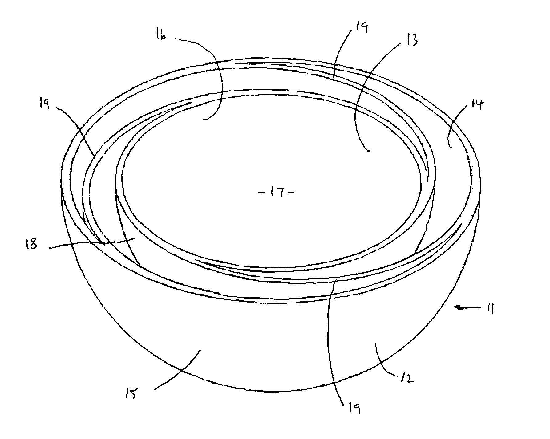
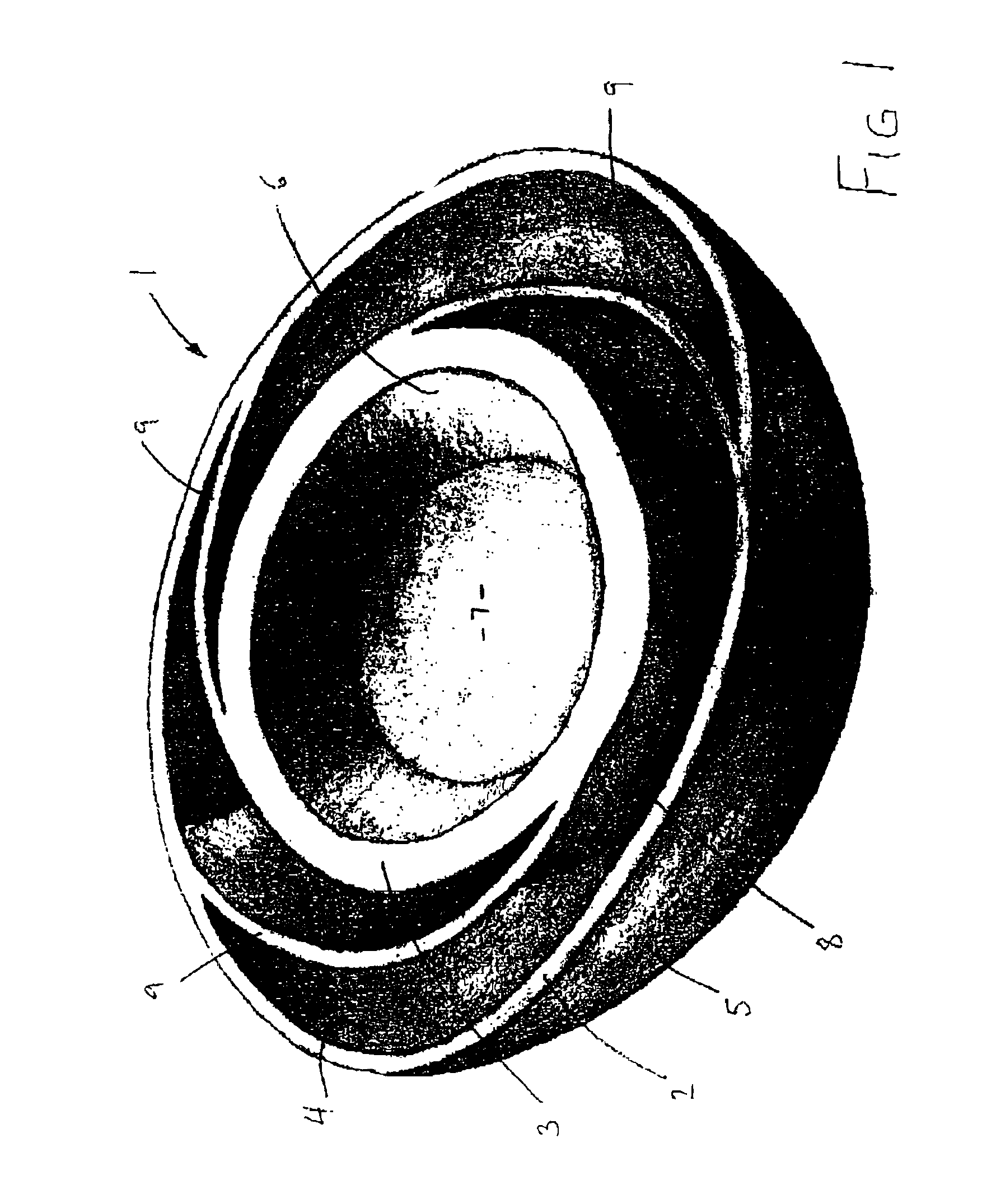
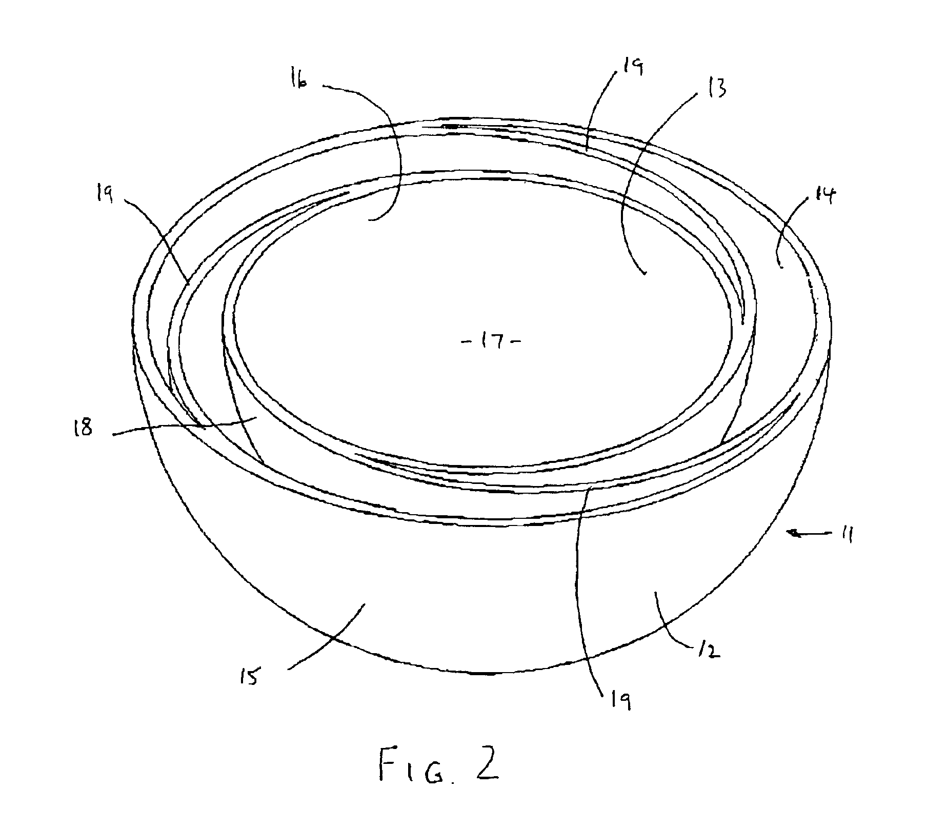
[0026]Referring to FIG. 1 of the drawings, an acetabular prosthesis 1 made of cobalt-chrome comprises an outer cup-shaped portion 2 and an inner cup-shaped portion 3. Inner portion 3 is nested within but spaced from outer portion 2. Outer portion 2 has a substantially concave inner surface 4 and a substantially convex outer surface 5, while inner portion 3 has a substantially concave inner surface 6, which defines a frusto-conical cavity 7, and a substantially convex outer surface 8. Flexible connecting means in the form of thin vanes 9 connect the outer convex surface 8 of the inner portion 3 to the concave inner surface 4 of the outer portion 2. Such a prosthesis can be made by stereolithography. The flexibility in vanes 9 will be dependent upon the thickness thereof. Hence different flexibilities can be achieved by utilising different thicknesses of vanes 9 or by varying the thickness of vanes 9 along their length.

[0027]Cavity 7 is intended for receipt of a ceramic or plastics ma...


PUM

PropertyMeasurementUnit
diameteraaaaaaaaaa
flexibleaaaaaaaaaa
biocompatibleaaaaaaaaaa

Abstract

The invention provides an acetabular prosthesis comprising an outer portion having a substantally concave inner surface and a substantially convex outer surface. An inner portion within and spaced from the outer portion and having a substantially concave inner surface defining a cavity and a substantially convex outer surface. Flexible connecting means, such as vanes, connect the outer convex surface of the inner portion to the concave inner surface of the outer portion. Such an acetabular prosthesis can exhibit matched compliance between the outer portion and the patient's pelvis while the inner portion accommodates idealised rigidity for artificial articulation components.

Description

BACKGROUND OF THE INVENTION[0001]This invention relates to an acetabular prosthesis.[0002]It is well known that a major factor influencing the life expectancy of a prosthetic implant is fatigue fracture and wear. Frictionally induced torque stresses acting through the prosthesis can result in the breakage of either the bone or the cement used to bond the prosthesis to the bone. For example, the pressure placed on an acetabular implant during the course of normal movement can be as high as several tonnes / cm2. Such loads may lead to a very high risk of failure of the implant. If a breakage of the hip bone or cement occurs, wear is inevitable. This can lead to particle formation which causes osteolysis and adverse tissue reactions. These factors not only reduce the life expectancy of a prosthesis but can cause considerable damage to the bone of the patient.[0003]Currently the life expectancy of an acetabular prosthesis is typically about ten years. If the prosthesis is to be implanted ...

Claims


Application Information

Patent Timeline
Patent Type & Authority Patents(United States)
IPC IPC(8): A61F2/32A61F2/34A61B17/68A61B17/86A61F2/00A61F2/30A61F2/46
CPCA61F2/34A61F2220/005A61F2230/0091A61F2250/0029A61F2250/0036A61F2250/0063A61F2310/00023A61F2310/00029A61F2310/00179A61F2310/00796A61B17/86A61F2/30724A61F2/30767A61F2/30965A61F2002/30018A61F2002/30291A61F2002/30324A61F2002/30329A61F2002/30332A61F2002/30448A61F2002/30563A61F2002/30573A61F2002/30611A61F2002/30962A61F2002/3411A61F2002/3438A61F2002/4631A61F2220/0025A61F2220/0033B33Y70/00B33Y80/00A61F2002/30014A61F2002/30604A61F2002/305A61F2002/30593
Inventor TAYLOR, ANDREW CLIVE
Owner FINSBURY DEV
Why Eureka
Try Eureka