
Bipolar discharge-dissipation lightning air terminals

a technology of air terminals and discharged discharges, applied in the installation of lighting conductors, connection to earth, relays, etc., can solve problems such as failure or malfunction, and achieve the effect of preventing the falling of thunderbolts

Active Publication Date: 2005-09-13
LEE TECH KOREA CO LTD
View PDF18 Cites 17 Cited by
  • Summary
  • Abstract
  • Description
  • Claims
  • Application Information

AI Technical Summary

Benefits of technology

[0008]Therefore, the present invention has been made in view of the above problem, and it is an object of the present invention to provide a bipolar discharge-dissipation lightning air-terminals for preventing the falling of a thunderbolt by discharging an earth charged charge following a thundercloud approach in a space on a top of a discharging member fixed on a protected building and decreasing an earth electric potential value to an electric field below a flashover voltage (FOV).

Problems solved by technology

However, there was a problem that, though the above-described conventional lightning air-terminals completely absorbs the impulse current due to the falling of the thunderbolt and discharges it safely to the ground, because the impulse current due to the falling of the thunderbolt is very great as described above, electronics products, building telecommunication equipment, computers, light electrical appliances, etc. may be subject to an inductive disturbance generated by the falling of the thunderbolt, thereby malfunctioning or being not working.

Method used


Image

  • Bipolar discharge-dissipation lightning air terminals
  • Bipolar discharge-dissipation lightning air terminals
  • Bipolar discharge-dissipation lightning air terminals

Examples


Embodiment Construction

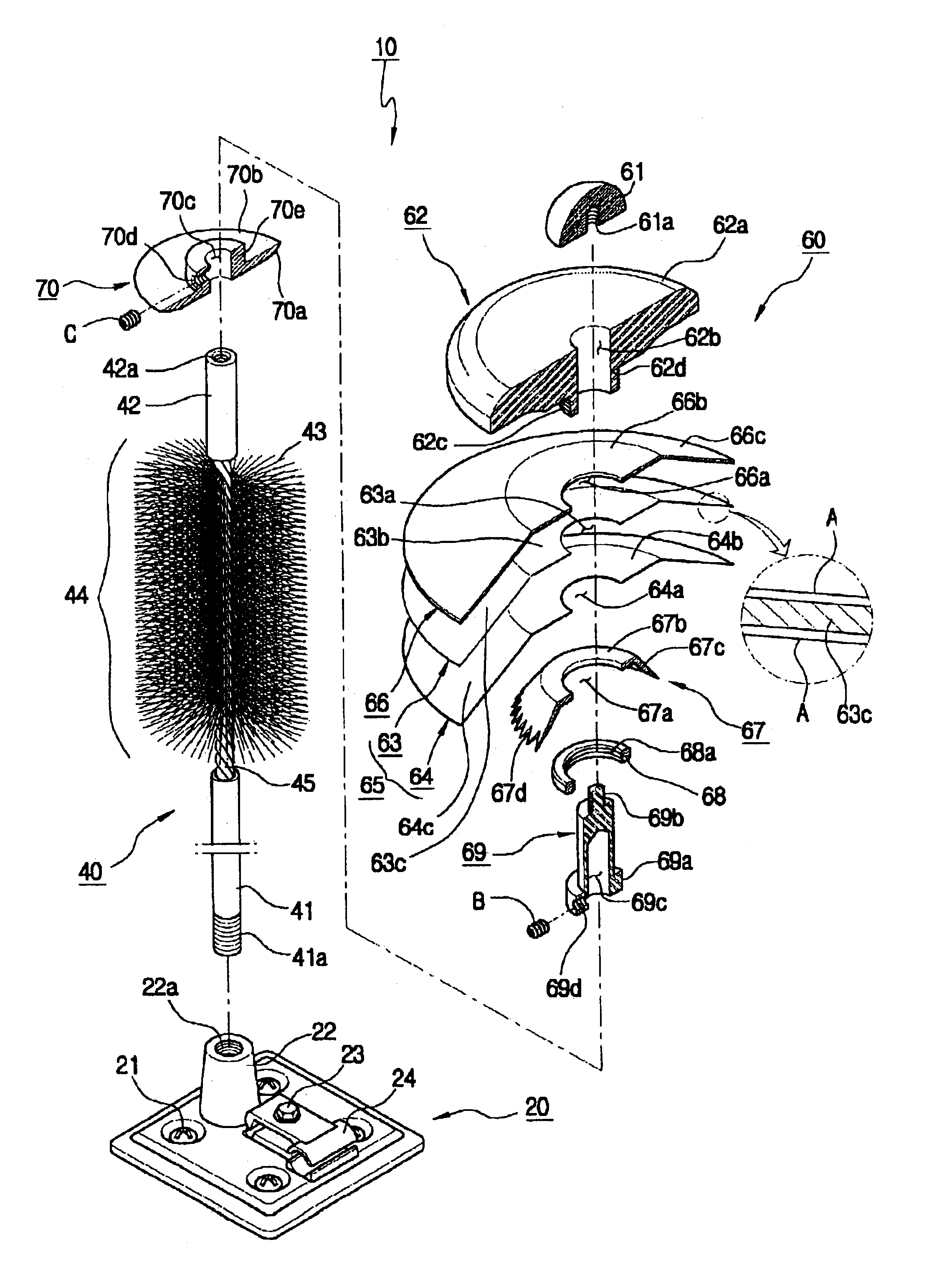
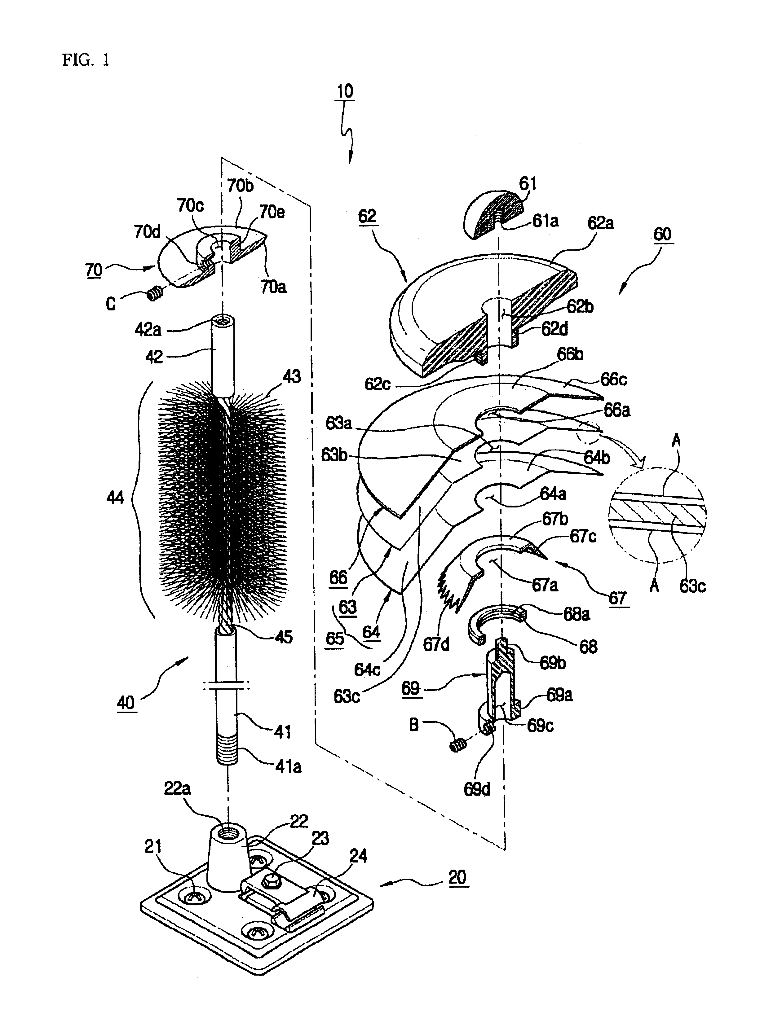
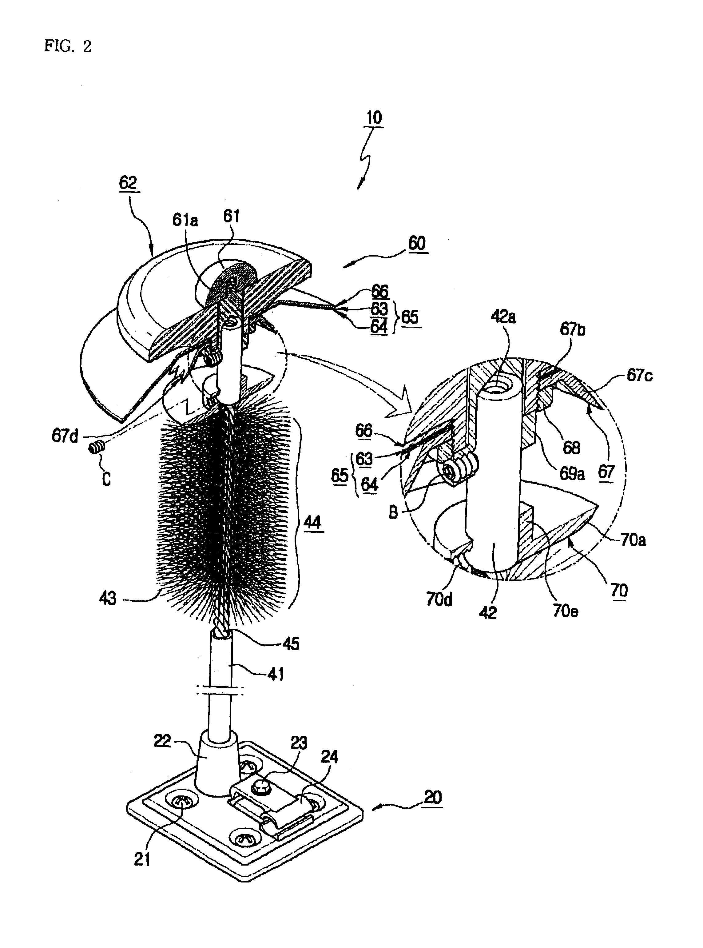
[0021]A preferred embodiment of the present invention will now be described with reference to the accompanying drawings. In the following description, same drawing reference numerals are used for the same elements even in different drawings. The matters defined in the description such as a detailed construction and elements of a circuit are nothing but the ones provided to assist in a comprehensive understanding of the invention. Thus, it is apparent that the present invention can be carried out without those defined matters. Also, well-known functions or constructions are not described in detail since they would obscure the invention in unnecessary detail.

[0022]Now, a preferred embodiment of the present invention will be described in detail with reference to the annexed drawings.

[0023]Before describing annexed drawings, it is noted that a basic concept of the present invention is to disperse and discharge an earth charge following a thundercloud approach in a space by including a p...


PUM


Abstract

The present invention relates to a Bipolar Discharge-Dissipation Lightning Air-Terminals, and an object of the present invention is to disperse and discharge an earth charge following a thundercloud approach in a space according to electric dipole, bipolar and electric double layer principle. The above object of the present invention is achieved by providing the bipolar discharge-dissipation lightning air-terminals comprising: a base member fixed and installed in a top region of a protected object, including a coupling projection on whose inner periphery surface coupling screw grooves are formed, the coupling projection protruded and formed at a side of an upper surface of the base member, and a grounding piece formed at a side opposite to the coupling projection in order to earth a ground electrode and a grounded lightning wire; a discharge member coupled releasably to the base member, for focusing an earth charge following a thundercloud approach on the upper surface of the base member; and a potential modifying unit attached releasably on the discharge member so that the potential modifying unit is charged with different charges by electric dipole, bipolar and electric double layer principle according to the thundercloud approach to disperse and discharge the earth charge in a space separated from the discharge member.

Description

BIPOLAR DISCHARGE-DISSIPATION LIGHTING AIR TERMINALS[0001]This application claims the priority of Korean Patent Application No. 2002-76020, filed Dec. 2, 2002, in the Korean Intellectual Property Office. The entire content of this application is incorporated herein by reference.BACKGROUND OF THE INVENTION[0002]1. Field of the Invention[0003]The present invention relates to a bipolar discharge-dissipation (charge transfer system) lightning air-terminals, and more particularly to a bipolar discharge-dissipation (charge transfer system) lightning air-terminals which is fixed-mounted on a top of a protected building in order to disperse and discharge an earth charged charge following a thundercloud approach in a space thereby preventing the falling of a thunderbolt.[0004]2. Description of the Related Art[0005]In general, a quantity of electricity which is generated upon the falling of a thunderbolt due to a thundercloud approach is approximately one billion volts (V) of voltage and at t...

Claims


Application Information

Patent Timeline
IPC IPC(8): H02G13/00
CPCH02G13/00H02G13/80H02G13/40
Inventor CHUNG, YOUNG-KI
Owner LEE TECH KOREA CO LTD
Learn More