High power electronic package with enhanced cooling characteristics

a technology of electronic packages and cooling characteristics, applied in the direction of cooling/ventilation/heating modifications, semiconductor device details, semiconductor devices, etc., can solve the problems of limited power-carrying capability of power switches, large modules, and large cost drivers of power electronics. achieve the effect of reducing power loss, increasing rate, and discharging hea

Active Publication Date: 2005-09-13
DELPHI TECH IP LTD
View PDF5 Cites 34 Cited by
  • Summary
  • Abstract
  • Description
  • Claims
  • Application Information

AI Technical Summary

Benefits of technology

[0007]An advantage of the present invention is that the electronic package can dissipate heat a...

Problems solved by technology

The modules are relatively large and costly.
A major cost driver for power electronics is the number and size of the power switches used.
The power-carrying capability of the power switches is limi...

Method used


Image

  • High power electronic package with enhanced cooling characteristics
  • High power electronic package with enhanced cooling characteristics
  • High power electronic package with enhanced cooling characteristics

Examples


Embodiment Construction

[0014]The embodiments discussed below are not intended to be exhaustive or limit the invention to the precise forms disclosed in the following detailed description. Rather, the embodiments are chosen and described so that others skilled in the art may utilize their teachings.

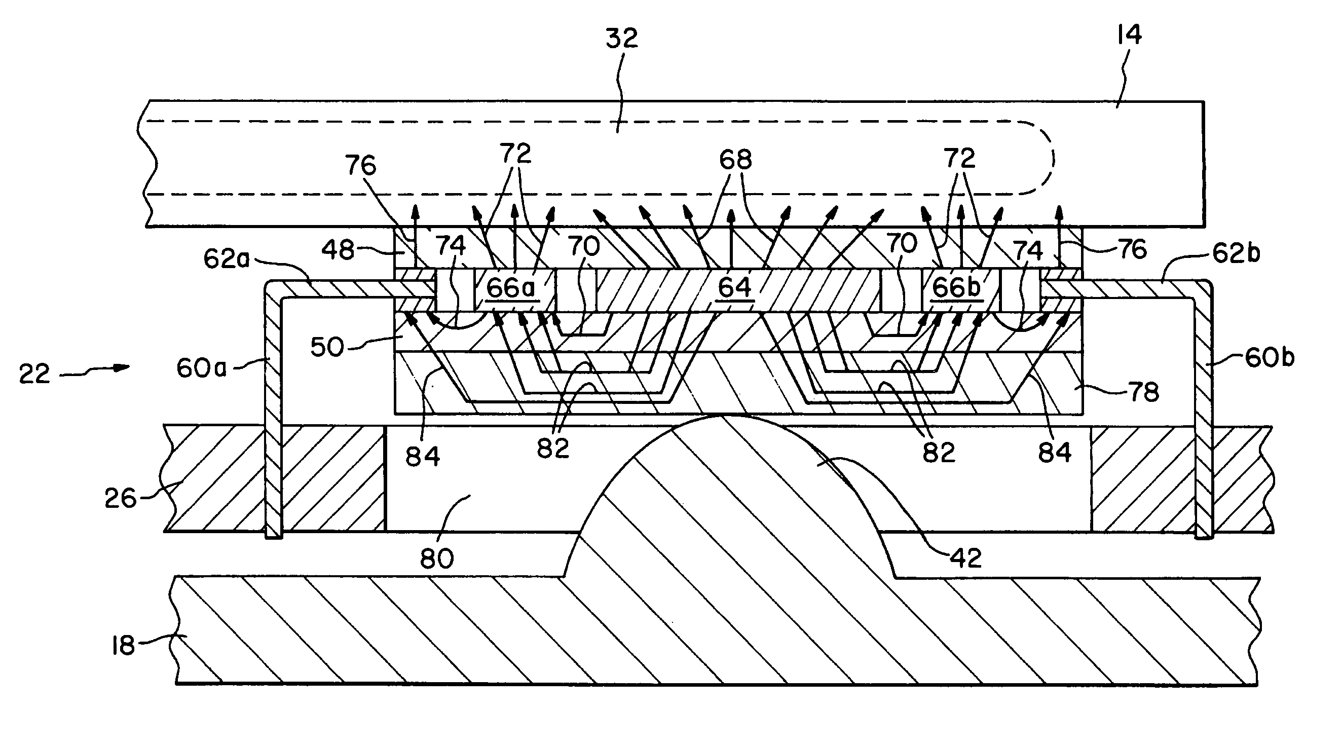
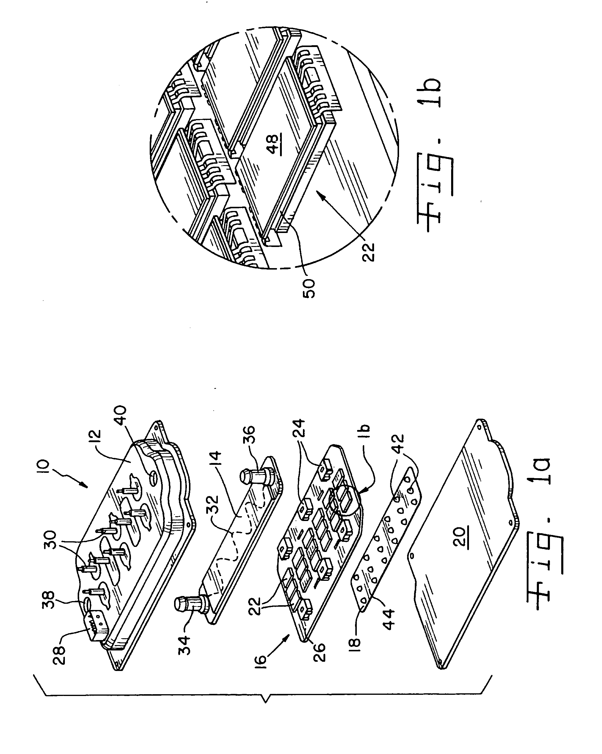
[0015]One embodiment of a power electronics module 10 of the present invention is shown in FIG. 1a. Module 10 includes a housing 12, a heat sink in the form of heat exchanger 14, a power board assembly 16, a biasing device 18, and a base 20. Heat exchanger 14, power board assembly 16 and biasing device 18 may be received in housing 12, and housing 12 may be attached to base 20 to form a container for protecting heat exchanger 14, power board assembly 16 and biasing device 18 therein.

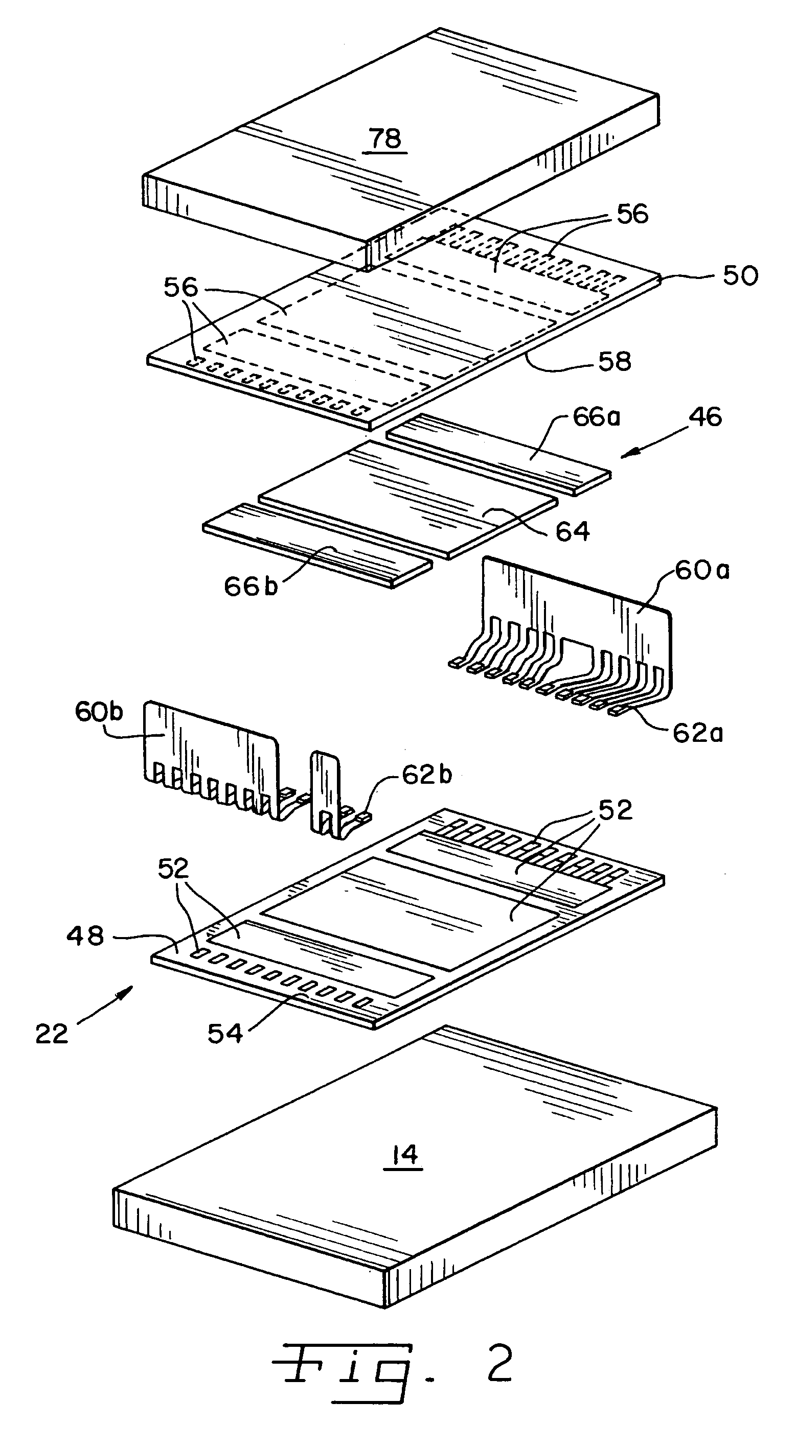
[0016]Power board assembly 16 includes an array of electronic packages 22 and input / output (I / O) devices 24 disposed on a circuit board 26. Packages 22 may be in electrical communication with each other and / or with I / O devices 24 via...


PUM


Abstract

A power electronics module includes a heat sink and an electronic package having a first layer in direct thermal communication with the heat sink. At least one electronic component is disposed between the first layer and a second layer. A thermally conductive element is in direct thermal communication with the second layer and carries heat from a first portion of the second layer to a second portion of the second layer such that the heat is transferred from the second portion of the second layer to the heat sink through the first layer.

Description

BACKGROUND OF THE INVENTION[0001]Electronic packages are used in many high power applications. For example, hybrid electric vehicles traditionally use power electronics modules, sometimes in the form of “inverters,” including electronic packages containing wire bonded power switches. The modules are relatively large and costly. A major cost driver for power electronics is the number and size of the power switches used.[0002]The number and size of the power switches required for a specific application may be determined by the power requirements of the application and the level of power density that each power switch is capable of carrying. The power-carrying capability of the power switches is limited by the rate at which heat may be dissipated from the power switches. Overheating of power switches, and electronics in general, is well known to cause a variety of performance problems in the device.[0003]What is needed in the art is a method of increasing the heat dissipating ability o...

Claims


Application Information

Patent Timeline
IPC IPC(8): H05K7/20H01L23/373H01L23/473H01L25/07
CPCH01L23/473H01L25/072H01L23/3735H01L2924/0002H01L2924/00
Inventor JETER, MICHAEL ATAYLOR, RALPH S.
Owner DELPHI TECH IP LTD
Why Eureka
Try Eureka