Robot spot welding apparatus for nuclear fuel skeleton and spot welding method using the same

Active Publication Date: 2005-09-13
KEPCO NUCLEAR FUEL CO LTD
View PDF3 Cites 13 Cited by
  • Summary
  • Abstract
  • Description
  • Claims
  • Application Information

AI Technical Summary

Benefits of technology

[0014]Therefore, it is an object of the present invention to perform welding, in particular, spot welding to spacer grids and guide and instrumentation tubes with a welding robot having a welding gun so as to maximize automation of a skeleton fabrication process, thereby enhancing productivity of the skeleton fabrication process.
[0017]It is yet another object of the present invention to provide a welding process which adopts a robot welding apparatus to minimize the operation of the robot arm in welding as well as shorten a fabrication time.

Problems solved by technology

In particular, the nuclear fuel skeletons require super high stability so that they can be directly inserted into the reactor and endure extreme conditions for a long time.
If TIG welding is performed in the air, zircaloy metal in a welding zone will combine with oxygen owing to its properties to potentially break the welding zone, thereby causing welding to be impossible.
This causes it to be difficult to obtain any welding angle as well as many risks that inter-electrode contact may occur in other skeleton regions during welding.
Further, automation of welding is difficult since every grid undergoes at least 40 points of welding in each tube.
Welding between the spacer grids and the guide and instrumentation tubes are still manually performed since a skeleton with the slightest defect is not reusable and such defects cause serious economical loss.
According to the above reasons, it has been required to automate the fabrication process of skeletons with poor productivity and high cost.

Method used


Image

  • Robot spot welding apparatus for nuclear fuel skeleton and spot welding method using the same
  • Robot spot welding apparatus for nuclear fuel skeleton and spot welding method using the same
  • Robot spot welding apparatus for nuclear fuel skeleton and spot welding method using the same

Examples


Embodiment Construction

[0033]The following detailed description will present a robot spot welding apparatus of the present invention with reference to the appended drawings. Although the specification will basically describe the spot welding apparatus for use in a KSNP skeleton shown in FIG. 2A and an ‘Advanced Fuel Skeleton’ shown in FIG. 2B, it is for illustrative purposes only but the scope of the invention shall not be restricted thereto.

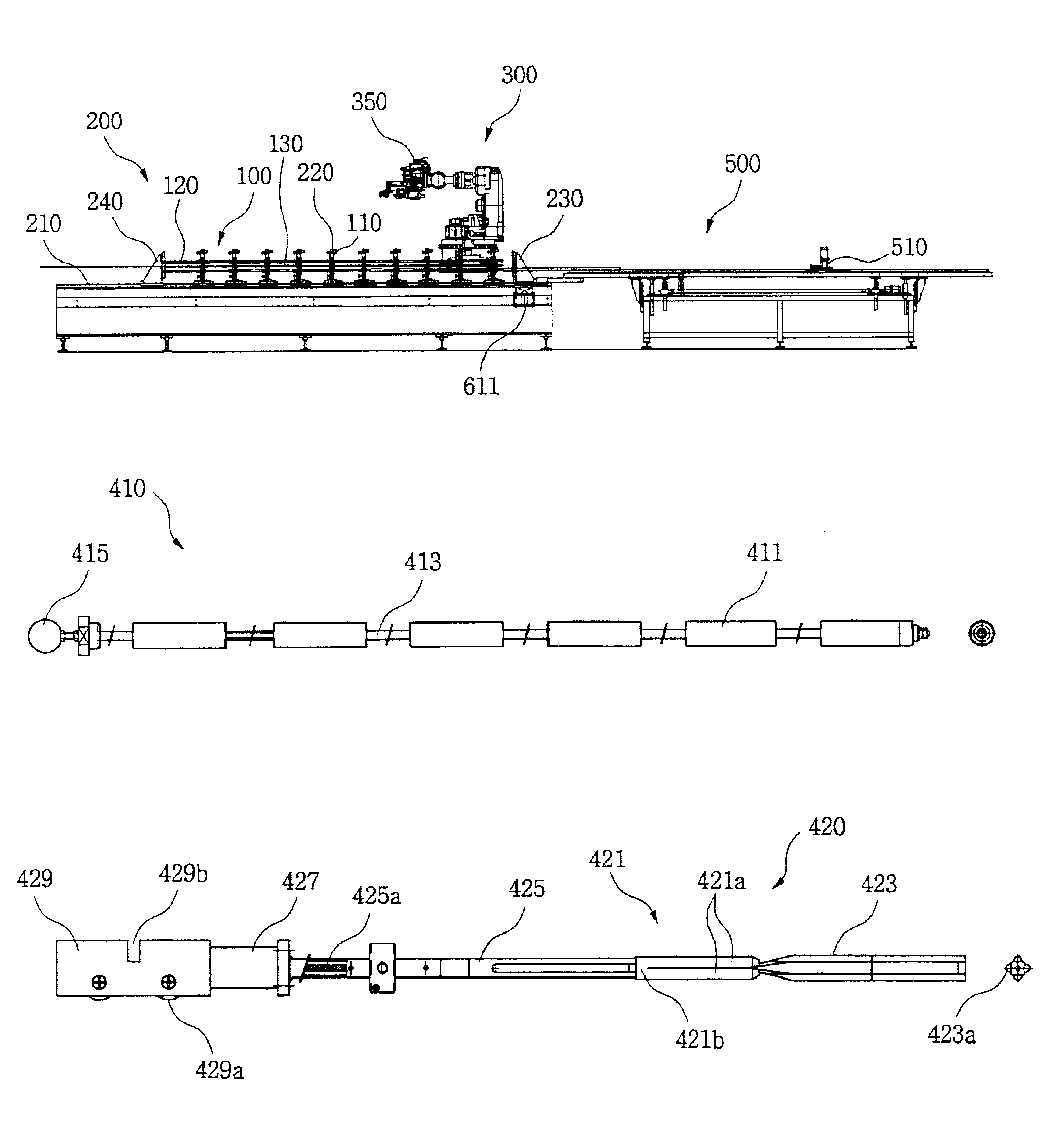
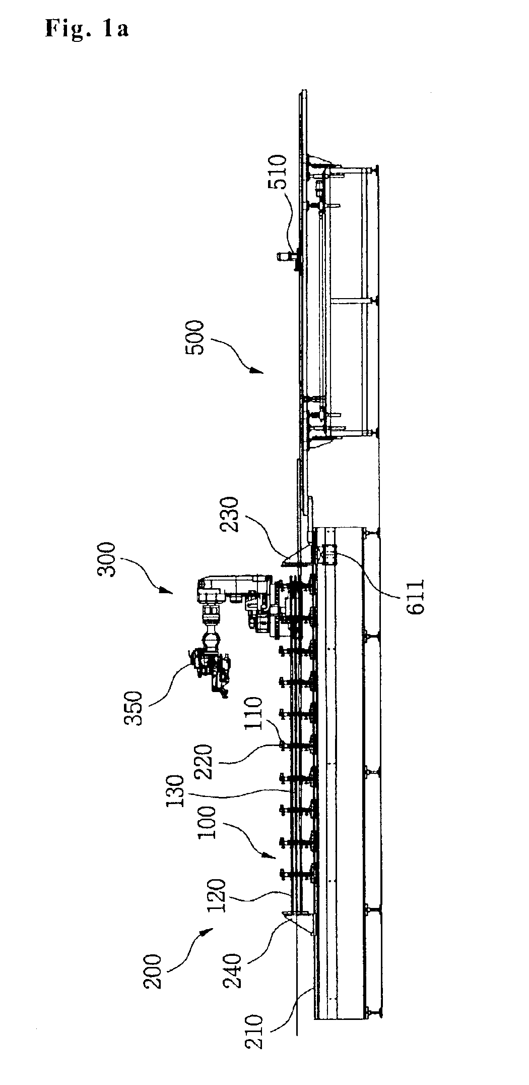
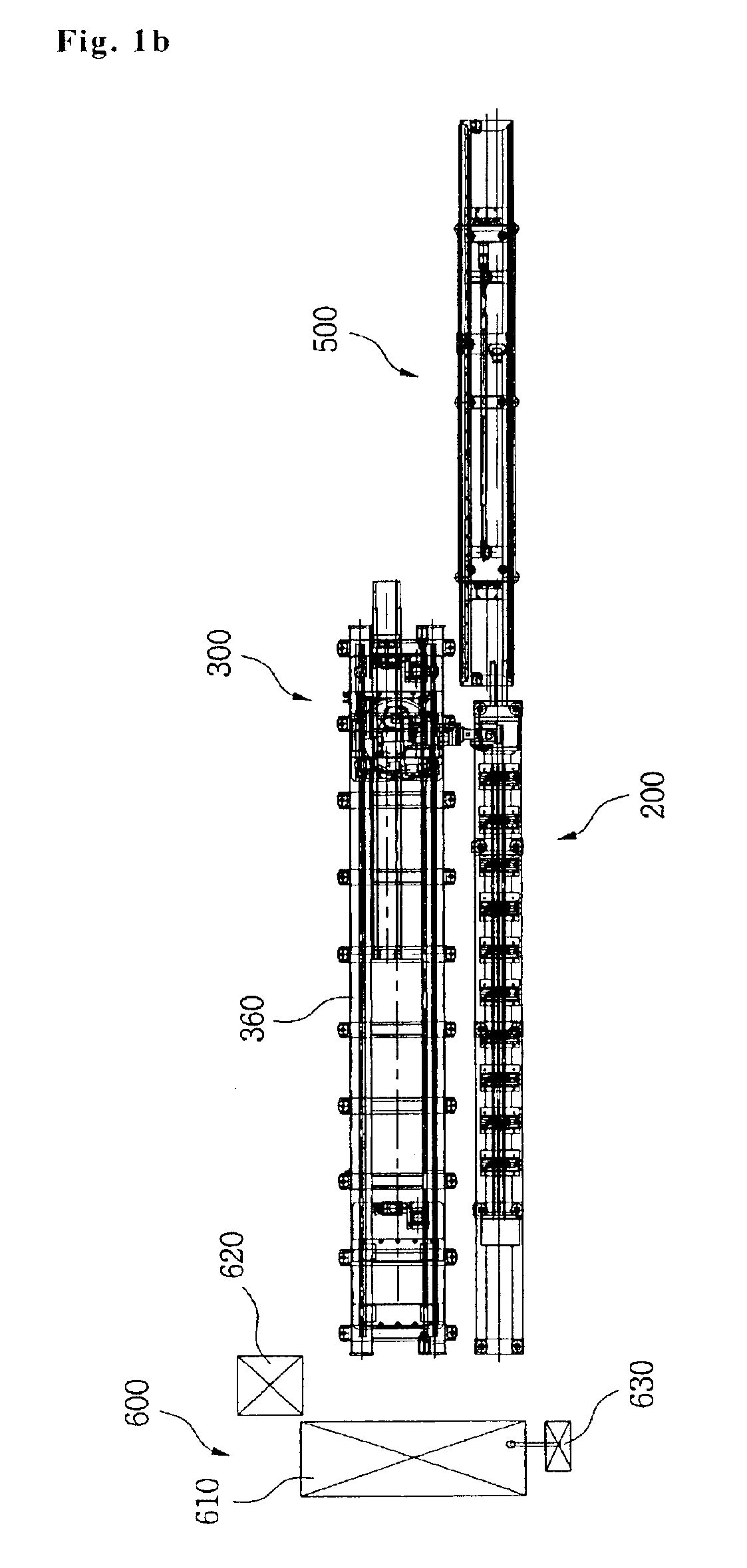
[0034]First, FIGS. 1A and 1B are front elevation and plan views illustrating an overall structure of a spot welding apparatus of the present invention.

[0035]The robot spot welding apparatus of the present invention generally comprises a welding bench 200, a robot 300, electrodes, a push table 500 and a controller 600. The welding bench 200 has clamping frames 220 which are spaced from one another according to a span of spacer grids 110 constituting a skeleton 100. The robot 300 is arranged in parallel at the rear of the welding bench 200 at the drawing and having a we...


PUM

PropertyMeasurementUnit
Diameteraaaaaaaaaa
Heightaaaaaaaaaa
Elasticityaaaaaaaaaa

Abstract

The automatic robot spot welding apparatus includes a welding bench including clamping frames, which are uniformly arrayed and have receiving portions for the sparer grids, and have, at both ends of the welding bench, fixing plates for the guide tubes and the instrumentation tube which are inserted into the spacer grids; a robot moving on a running rail, which is arranged in parallel to the welding bench, and having a welding gun for welding the spacer grids with the guide and instrumentation tubes; guide tube electrodes for being inserted into the guide tubes for the spot welding; an instrumentation tube electrode for being inserted into the instrumentation tube; and a controller having an apparatus control block and a robot control block for controlling components based on a program stored therein.

Description

BACKGROUND OF THE INVENTION[0001]1. Field of the Present Invention[0002]The present invention relates to a welding apparatus and a welding method for a nuclear fuel skeleton which is fabricated by welding guide tubes for power control rods and an instrumentation tube for measuring fuel to spacer grids having a plurality of cells, into which fuel rods are inserted. In particular, the welding apparatus and the welding method allow a robot having a welding gun to automatically spot-weld the guide tubes and the instrumentation tubes to the spacer grids.[0003]2. Background of the Related Art[0004]A nuclear fuel skeleton is a support structure for receiving fuel rods inserted into a reactor of a nuclear power plant as well as allowing inspection to reaction status of nuclear fuel. The skeleton includes spacer grids having a plurality of cells for the fuel rods and arranged at a certain span, guide tubes for control rods to be inserted into insert holes in the spacer grids and an instrumen...

Claims


Application Information

Patent Timeline
IPC IPC(8): B23K37/02B23K11/11
CPCB23K37/0235B23K2201/04B23K2101/04B23K11/11
Inventor CHO, SANG HYUNHWANG, CHANG HWANCHOI, YONG SHINSHIN, DONG YOON
Owner KEPCO NUCLEAR FUEL CO LTD
Why Eureka
Try Eureka