Clutch protection system

a technology for protecting systems and clutches, applied in mechanical equipment, transportation and packaging, instruments, etc., can solve problems such as premature wear and damage of clutches, and achieve the effect of reducing the amount of energy dispersed

Inactive Publication Date: 2005-09-13
EATON INTELLIGENT POWER LIMITED
View PDF15 Cites 11 Cited by
  • Summary
  • Abstract
  • Description
  • Claims
  • Application Information

AI Technical Summary

Benefits of technology

[0005]The present invention relates to a vehicle clutch protection system, comprising a monitor for monitoring an operating state of a clutch, an estimator for estimating an amount of energy dissipated by the clutch, and a comparator that compares the estimated amount of diss

Problems solved by technology

This spinning of the two plates at different speeds is what results in wear and damage to the clu

Method used


Image

  • Clutch protection system
  • Clutch protection system
  • Clutch protection system

Examples


Embodiment Construction

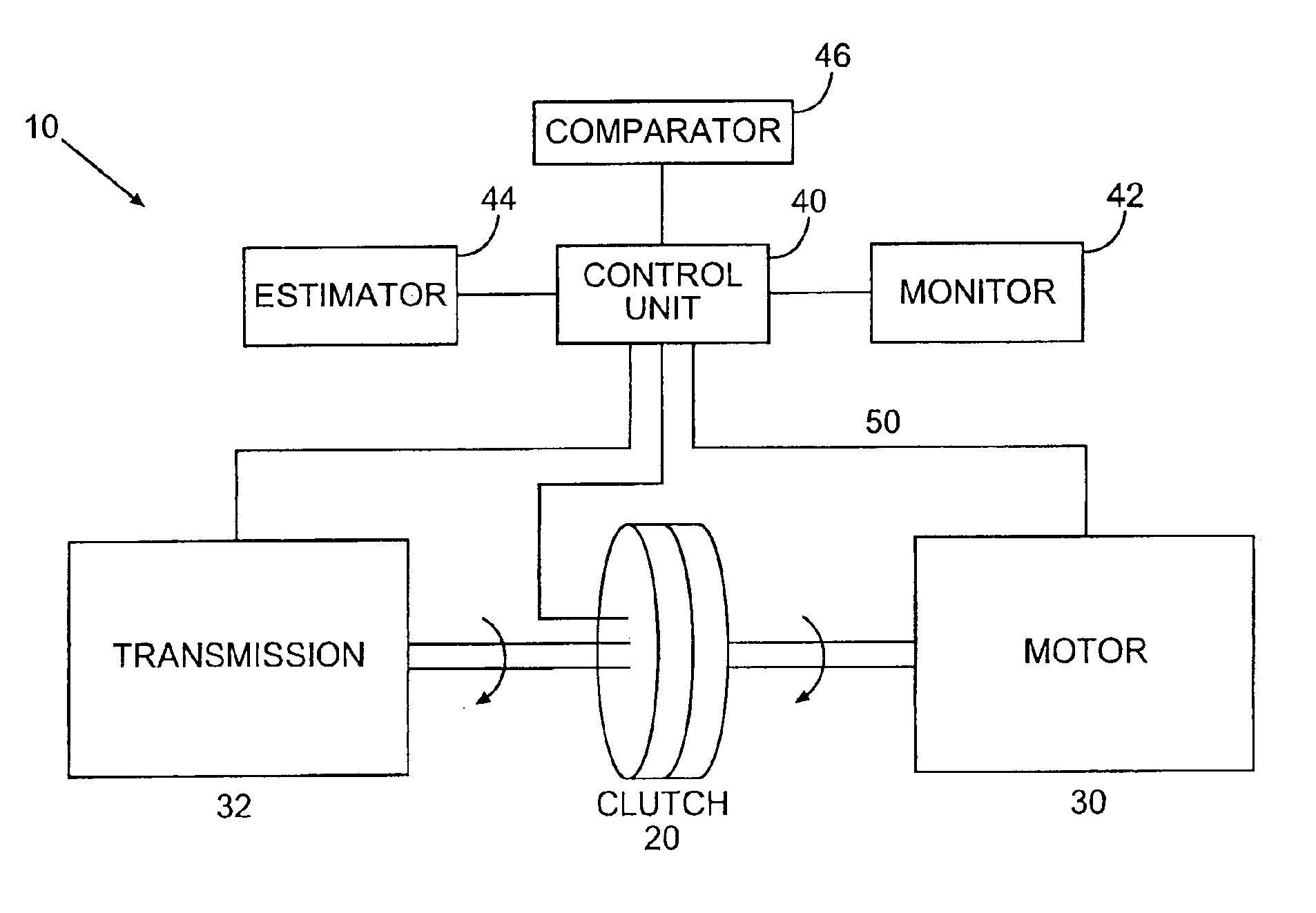
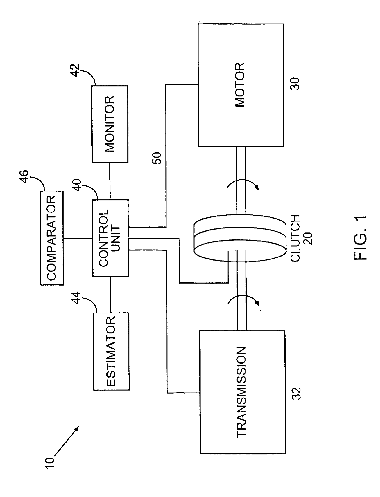
[0011]FIG. 1 depicts the vehicle clutch protection system 10 according to one embodiment of the present invention. A transmission 32, such as an automatic transmission, is selectively engaged to a motor 30 by means of clutch 20. Transmission 32 may be any type of transmission typically found in a vehicle, for example, the Autoshift™ system made by Eaton Corporation. Additionally, transmission 32 may have the capability to be placed in a manual operating mode, thereby allowing the operator of a vehicle to determine when transmission 32 will actually shift to another gear. Motor 30 can be any type of motor used to propel a vehicle. Typically this will be an internal combustion engine, although other types of motors, such as an electric motor, may just as easily be used with the present invention. In the illustrated embodiment, clutch 20 is a wet clutch, which typically relies on oil not only as a lubricant but also as a coolant. Of course, the clutch protection system can be adapted t...


PUM


Abstract

A system for protecting the clutch of a vehicle from a harmful operating state. Included in the clutch protection system are means for monitoring the operating state of the clutch, along with means for estimating the amount of energy being dissipated by the clutch. A control unit compares the estimated amount of energy dissipated by the clutch to one or more predetermined threshold energy levels. One or more actions designed to reduce the amount of energy dissipated by the clutch are initiated when the estimated amount of energy dissipated by the clutch exceeds the one or more predetermined thresholds.

Description

FIELD OF THE INVENTION[0001]The present invention relates to a clutch of a vehicle, and, more specifically, a system and method for protecting the clutch from excessive wear and potential damage.BACKGROUND OF THE INVENTION[0002]A clutch is a mechanism designed to connect or disconnect power from one working part to another. In terms of vehicles, the clutch is used to transmit power from the motor to the drive train, and to disengage the motor and transmission when shifting gears.[0003]In its simplest form, the clutch can be considered as comprising two plates that can be selectively placed up against one another. One plate (flywheel) is attached to and rotated by a motor. A counterpart plate (clutch plate) attaches to a system of gears that one wants to run with the power of the motor. To transfer the power of the motor to the gears, the clutch plate is pushed up against the rotating flywheel. Upon being pressed up against one another, the two plates don't initially spin in synch. I...

Claims


Application Information

Patent Timeline
IPC IPC(8): F16D48/00F16D48/06
CPCF16D48/06Y10T477/653Y10T477/6934Y10T477/6395F16D2500/31453F16D2500/5023F16D2500/50296F16D2500/7041F16D2500/70434F16D2500/7044F16D2500/70488F16D2500/7103F16D2500/7104B60W2050/143
Inventor MACK, WILLIAM J.
Owner EATON INTELLIGENT POWER LIMITED
Why Eureka
Try Eureka