Adjustable alarm device for sliding doors and windows

an alarm device and sliding door technology, applied in the direction of burglar alarm mechanical actuation, burglar alarm by opening, instruments, etc., can solve the problems of reducing the usefulness and marketability of the device, reducing the cost of manufacture, and complex mechanical devices

Inactive Publication Date: 2005-09-13
ALLEN ROBERT
View PDF13 Cites 129 Cited by
  • Summary
  • Abstract
  • Description
  • Claims
  • Application Information

AI Technical Summary

Benefits of technology

[0016]The cam body has a first unlocked position with respect to the inner surface of the elongate outer first tube and a second locked position with respect to the inner surface of the elongate outer first tube. In the first unlocked position, the cam body skirt is disengaged from the inner surface of the elongate outer first tube and the laterally projected protuberance is in fictional contact with the inner surface of the elongate outer first tube thereby permitting controlled sliding movement between the elongate outer first tube and the elongate inner second tube. In the second releasably locked position, the cam body skirt is in tight frictional engagement with the inner surface of the elongate outer first tube thereby prohibiting any relative movement between the elongate outer first tube and the elongate inner second tube. The cam body is moved from an unlocked position to releasably locked position by twisting the elongate outer first tube and the elongate inner second tube in opposite directions thereby causing the cam body to rotate on the journal which in turn causes the cam body skirt to frictionally engage the inner surface of the elongated first outer tube. The cam body is moved from a releasabl

Problems solved by technology

Many homes and businesses are victimized by intruders that gain unauthorized access through doors and windows.
However, many of these devices are mechanically complex and therefore expensive

Method used


Image

  • Adjustable alarm device for sliding doors and windows
  • Adjustable alarm device for sliding doors and windows
  • Adjustable alarm device for sliding doors and windows

Examples


Embodiment Construction

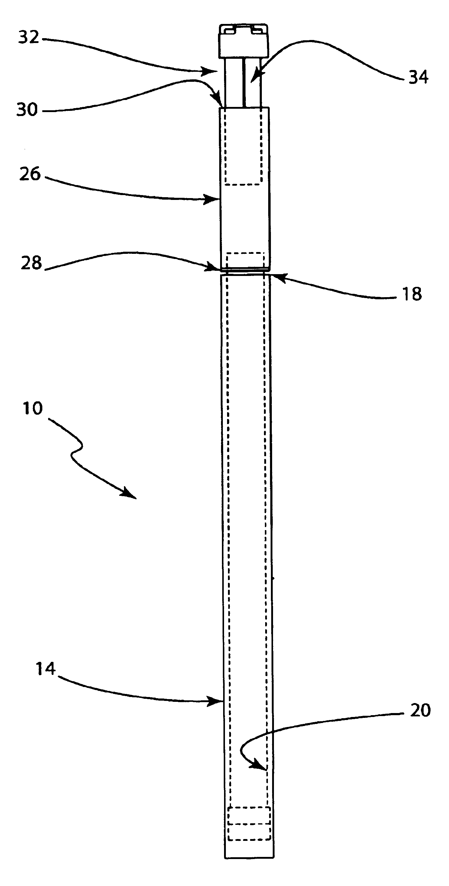
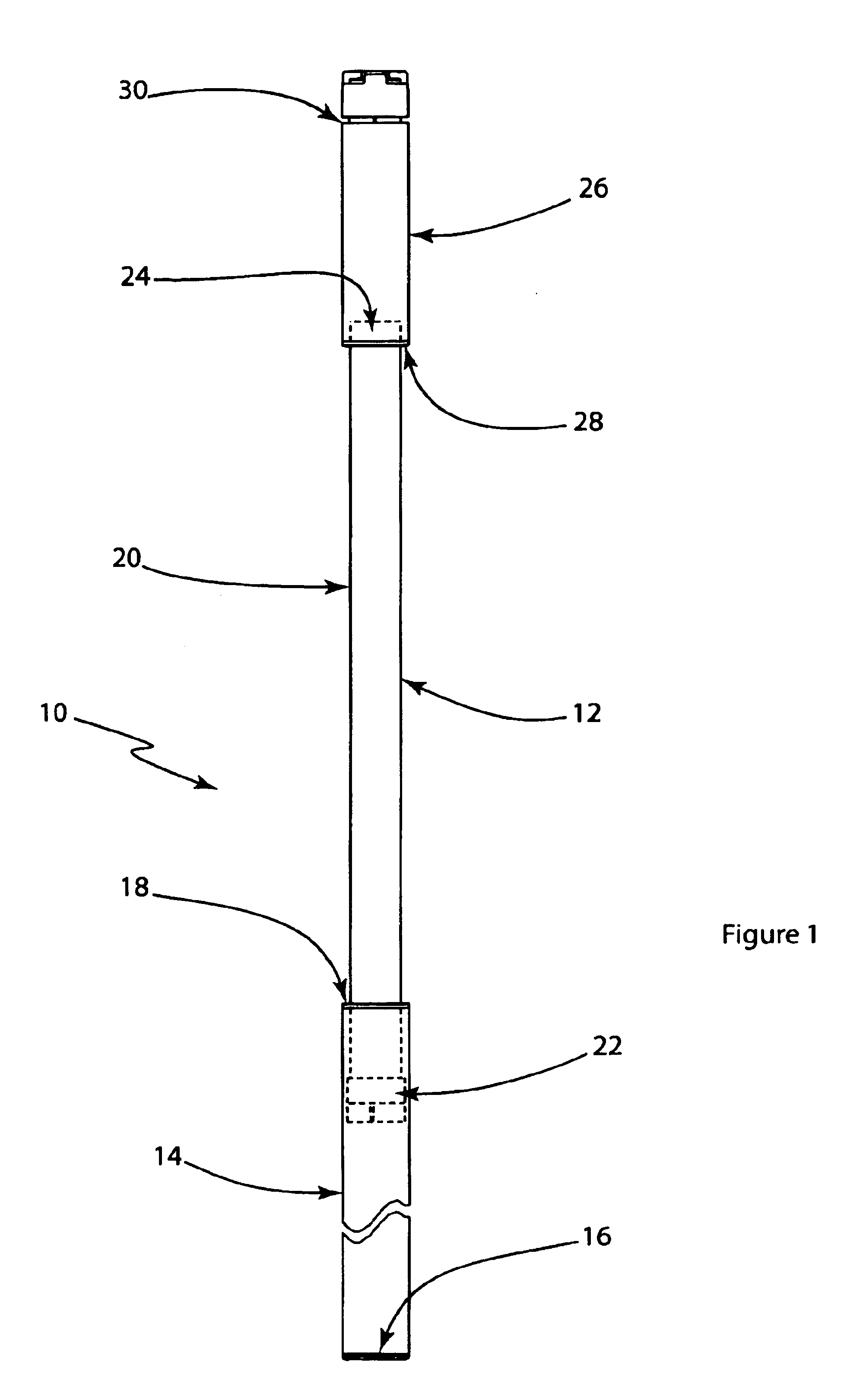
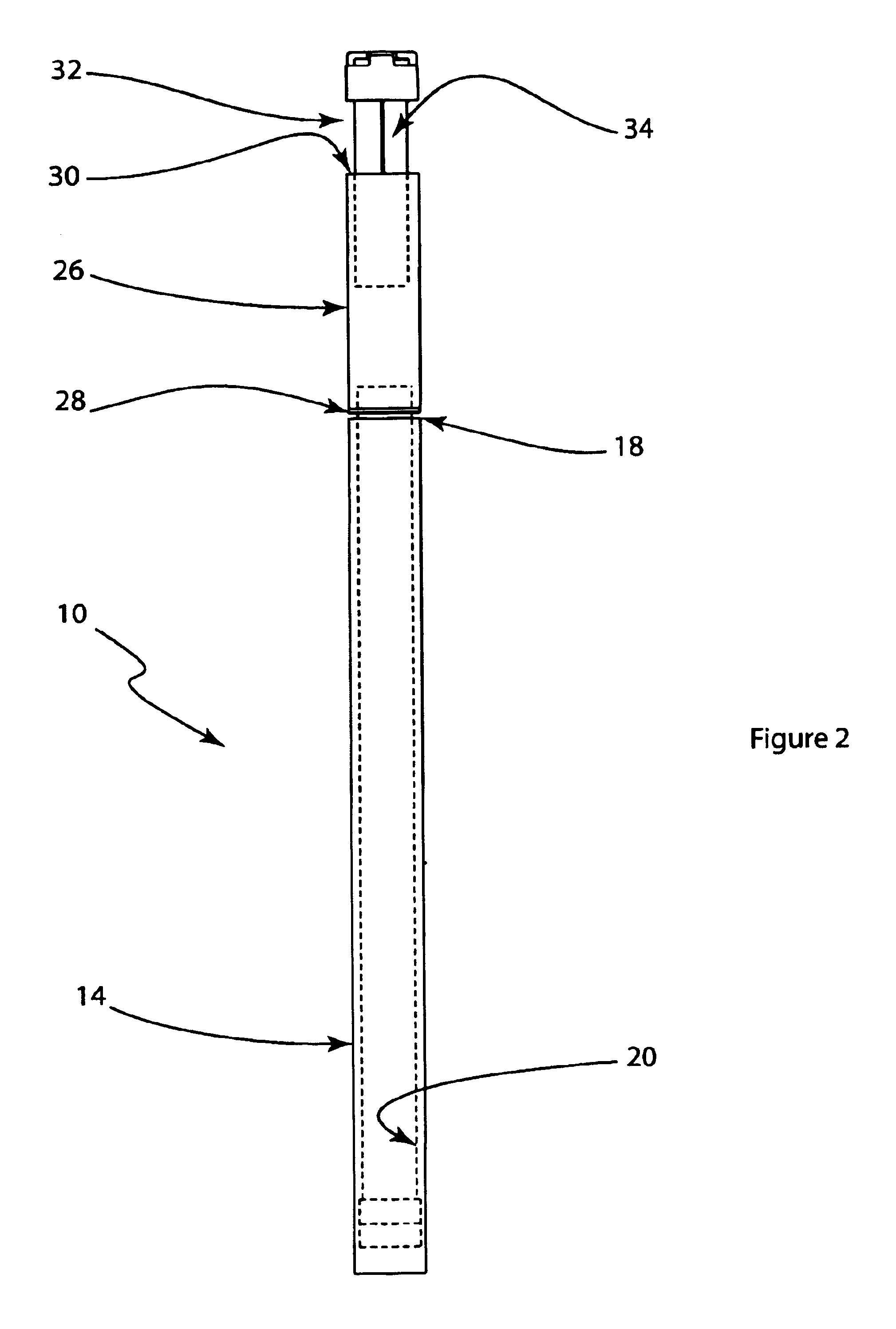
[0065]Referring to FIG. 1, there is shown a preferred embodiment of the invention. An adjustable alarm device for windows and doors is shown generally as (10). The alarm device has an elongate tubular telescoping body shown generally as (12) comprising an elongate outer first tube (14) having a first end (16) and a second end (18). In FIG. 1, the elongate outer first tube (14) is depicted in a truncated fashion for illustration purposes only. The alarm device further comprises an elongate inner second tube (20) having a first end (22) and a second end (24). The elongate inner second tube (20) is slidingly received within the elongate outer first tube (14). The second end (24) of the elongate inner second tube (20) extends from the first end (18) of the elongate outer first tube (14).

[0066]The invention (10) also includes means for releasably locking the elongate inner second tube (20) positionally with respect to the elongate outer first tube (14). For example, as depicted in FIG. 1...


PUM


Abstract

An adjustable alarm device for windows and doors is installed between the door or window frame and the door or window sash. The longitudinal axis of the alarm device is preferably horizontal. When engaged, movement of the door or window in an open direction will activate the alarm. The body of the alarm device is elongate, tubular and telescoping. The body comprises an outer tube that receives an inner tube. The body of the alarm device may be locked in an extended position by way of a cam mounted on the inner tube and positioned within the body so that when the inner and outer tubes of the body are twisted about their longitudinal axis, the cam body will engage the inner surface of the outer tube in a releasable frictional locking engagement. The alarm device is coupled to one end of the inner tube.

Description

CROSS REFERENCE TO RELATED APPLICATIONS[0001]This application claims the benefit of U.S. Provisional Patent Application 60 / 336,173 filed on Dec. 6, 2001.BACKGROUND[0002]1. Field of the Invention[0003]This invention relates to devices for intrusion detection through doors and windows and more specifically relates to an adjustable alarm device for sliding doors and windows.[0004]2. Background of the Invention[0005]Many homes and businesses are victimized by intruders that gain unauthorized access through doors and windows. There are several patents that disclose a variety of devices that provide for locks and alarms for sliding doors and windows. However, many of these devices are mechanically complex and therefore expensive to manufacture. For example, U. S. Pat. No. 6,388,572 “Selectively Positional Intruder Alarm for Sliding Windows and Doors” issued to Salter on May 14, 2002 discloses a portable device for sliding doors and windows. This device requires specially shaped ends to en...

Claims


Application Information

Patent Timeline
IPC IPC(8): G08B13/08G08B13/02
CPCG08B13/08
Inventor ALLEN, ROBERT
Owner ALLEN ROBERT
Why Eureka
Try Eureka