Early primitive assembly and screen-space culling for multiple chip graphics system

a graphics system and chip technology, applied in the field of computer graphics, can solve the problems of reducing the amount of data transferred between chips and disrupting the efficiency of its processes

Inactive Publication Date: 2005-09-13
ORACLE INT CORP
View PDF5 Cites 12 Cited by
  • Summary
  • Abstract
  • Description
  • Claims
  • Application Information

AI Technical Summary

Benefits of technology

[0007]Incorporating a primitive assembler (also referred to herein as a primitive assembly unit) in both the geometry chip and the rasterization chip may provide a new solution to the problems outlined above. A multi-chip system and method are disclosed for incorporating a primitive assembler in each of one or more geometry chips and one or more rasterization chips. This system may allow per-primitive operations to be performed in the geometry chips, and also allow use of geometry compression of vertex data when sending vertex data to the rasterization chips. Geometry compression provides a method for sending data for a vertex only once, even if it resides in more than one primitive. The primitive assemblers in the geometry chips may assemble vertices into primitives for clipping tests. The geometry chips may also test an assembled primitive against the projected boundaries of a set of screen space regions, where each region is assigned to one of the rasterization chips. Those primitives residing in more than one region may be sub-divided into two or more new primitives so that each new primitive resides in only one screen space region. The geometry chip may then send the vertex data for each primitive to the corresponding rasterization chip.

Problems solved by technology

This may reduce the amount of data transferred between chips since a vertex may be used in more than one triangle and that vertex need only be transmitted once, but may be reused one or more times. However, primitives requiring clipping would be returned to the geometry chip and may disrupt the efficiency of its processes.

Method used


Image

  • Early primitive assembly and screen-space culling for multiple chip graphics system
  • Early primitive assembly and screen-space culling for multiple chip graphics system
  • Early primitive assembly and screen-space culling for multiple chip graphics system

Examples


Embodiment Construction

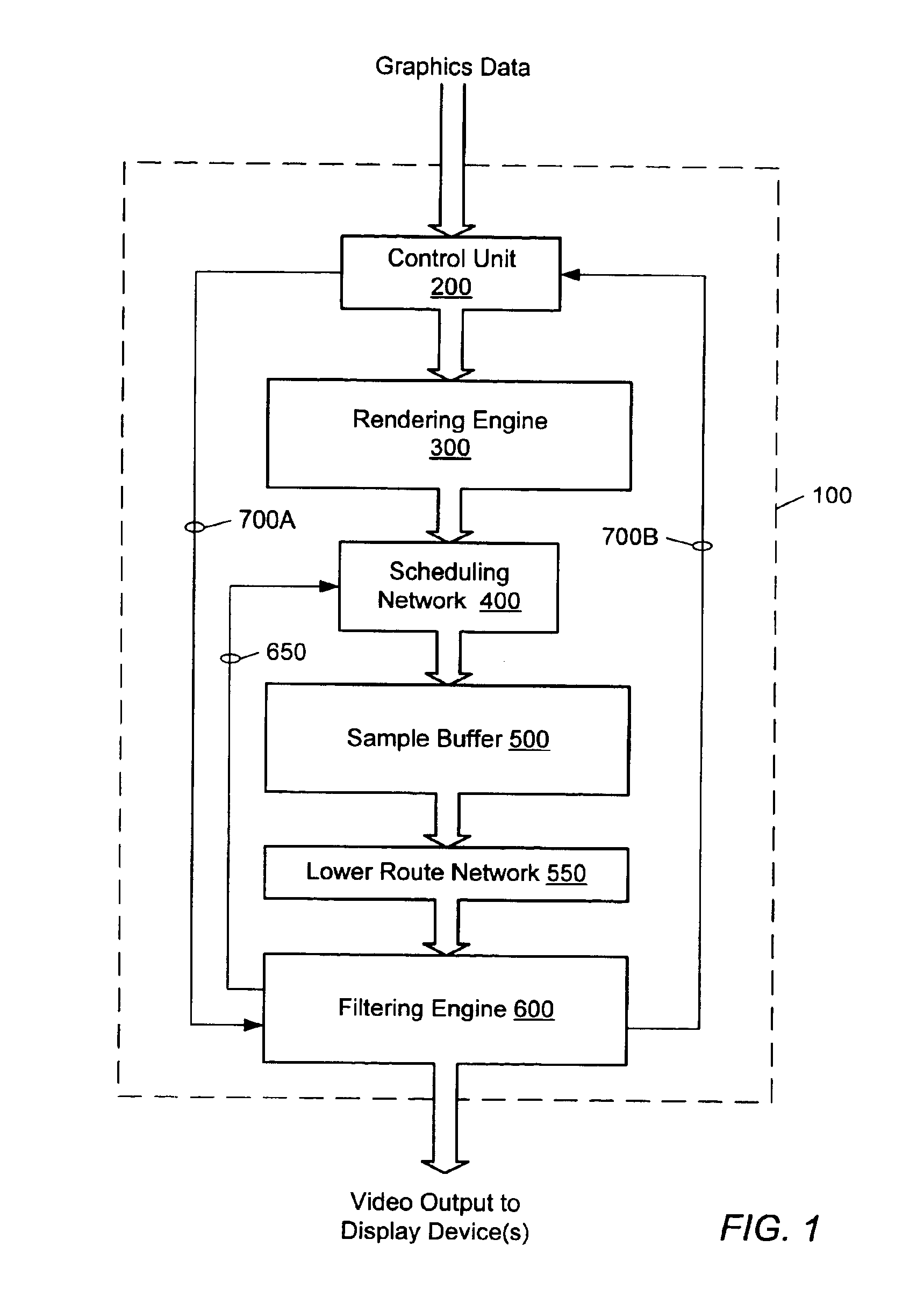
[0035]FIG. 1 illustrates one set of embodiments of a graphics accelerator 100 configured to perform graphics computations (especially 3D graphics computations). Graphics accelerator 100 may include a control unit 200, a rendering engine 300, a scheduling network 400, a sample buffer 500, a lower route network 550, and a filtering engine 600.

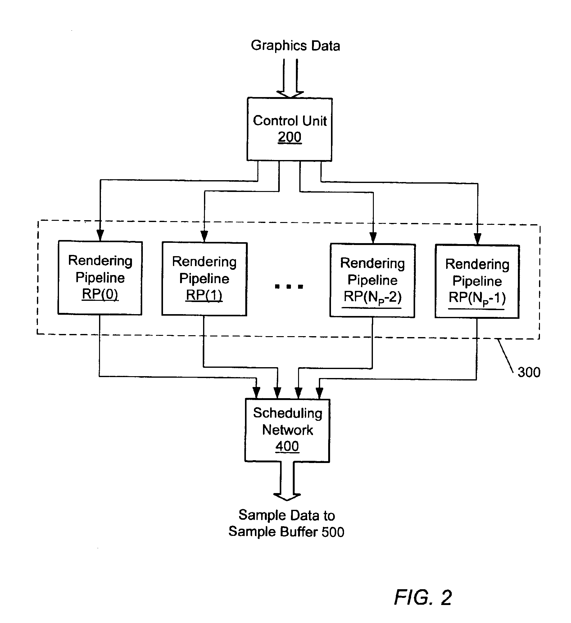
[0036]The rendering engine 300 may include a set of NPL rendering pipelines as suggested by FIG. 2, where NPL is a positive integer. The rendering pipelines, denoted as RP(0) through RP(NPL−1), are configured to operate in parallel. For example, in one embodiment, NPL equals four. In another embodiment, NPL=8.

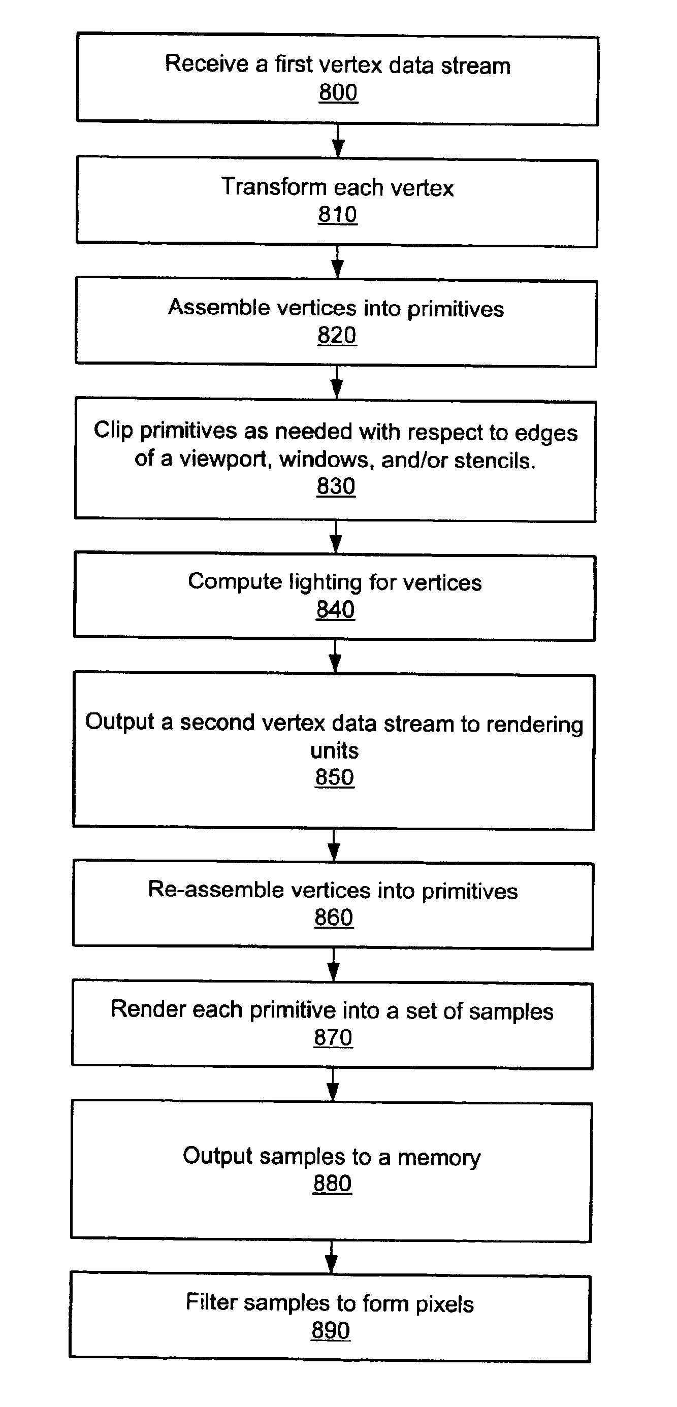
[0037]The control unit 200 receives a stream of graphics data from an external source (e.g. from the system memory of a host computer), and controls the distribution of the graphics data to the rendering pipelines. The control unit 200 may divide the graphics data stream into NPL substreams, which flow to the NPL rendering pipelines respecti...


PUM


Abstract

A multi-chip system and method are disclosed for incorporating a primitive assembler in each of one or more geometry chips and one or more rasterization chips. This system may allow per-primitive operations to be performed in the geometry chips, and also allow use of a vertex data interface for sending vertex data to the rasterization chips. The primitive assemblers in the geometry chips may assemble vertices into primitives for clipping tests. The geometry chips may also test an assembled primitive against the projected boundaries of a set of screen space regions, where each region is assigned to one of the rasterization chips. Those primitives residing in more than one region may be sub-divided into two or more new primitives so that each new primitive resides in only one screen space region. The geometry chip may then send the vertex data for each primitive to the corresponding rasterization chip.

Description

BACKGROUND OF THE INVENTION[0001]1. Field of the Invention[0002]This invention relates generally to the field of computer graphics and, more particularly, to a high performance graphics system.[0003]2. Description of the Related Art[0004]High performance graphics systems may include a floating-point processor (geometry chip) that performs operations such as transformation and lighting, and a rasterization chip that performs operations such as primitive assembly, clipping, and rasterization of primitives.[0005]Graphics APIs support the use of a number of primitives that are composed of vertices such as triangles, quadrangles, and polygons, and sets of primitives such as triangle strips and triangle fans. Most graphics accelerators sub-divide the higher order primitives (strips, fans, quadrangles, and polygons) into triangles and then rasterize the triangles.[0006]Some operations are performed on each vertex, and some operations are performed on assembled triangles. Primitive assembly...

Claims


Application Information

Patent Timeline
Patent Type & Authority Patents(United States)
IPC IPC(8): G06T1/20G06T1/60G06T15/00
CPCG06T1/60G06T15/005H04N19/80H04N19/42
Inventor WASSERMAN, MICHAEL A.KUBALSKA, EWA M.EMBERLING, BRIAN D.
Owner ORACLE INT CORP
Why Eureka
Try Eureka