Optical component and dispersion compensation method

a technology of optical components and compensation methods, applied in the direction of optical elements, instruments, optical waveguide light guides, etc., can solve the problems of insufficient compensation of the second order dispersion only during transmission, serious problem of dispersion in signal light transmitting through optical fibers, placed on optical communications,

Inactive Publication Date: 2005-09-13
OYOKODEN LAB +1
View PDF6 Cites 26 Cited by
  • Summary
  • Abstract
  • Description
  • Claims
  • Application Information

AI Technical Summary

Benefits of technology

[0030]that the reflectance relative to the center wavelength 1 of incident light of each reflective layer of the multi-layer film gradually becomes larger from one side of the multi-layer film in the direction of film thickness of the multi-layer film.

Problems solved by technology

In such an environment, the dispersion that occurs in a signal light transmitting through optical fibers becomes a serious problem, and various attempts have been made to compensate for that dispersion.
However, as the demands being placed on optical communications become increasingly severe, compensation of the second order dispersion only during transmission has become insufficient, and compensation of the third order dispersion is becoming an important topic.
The signal light that is deformed in this way may be unable to be accurately received as a signal light as a result of being unable to be distinguished from the signal light before and after it in, for example, high speed communications or long distance transmissions.
However, in a compensation method for the second order wavelength dispersion of the prior art described above that uses a dispersion compensating fiber, dispersion compensation of signal light that has been transmitted along a transmission path cannot be performed in the state of the signal light prior to being input into the transmission path, namely until the shape of graph 501, and that compensation is limited to until the shape of graph 503.
These phenomena are becoming serious problems including the prevention of accurate signal reception accompanying greater needs for longer transmission distances and faster communication speeds of optical communications.
For example, in the case of high speed communications in which signals are transmitted at a communications bit rate of 40 Gbps (40 gigabits per second) over a distance of 10,000 km or higher speed communications in which signals are transmitted at 80 Gbps over a distance on the order of several thousands km, these phenomena are a cause of considerable concern and are viewed as extremely serious problems.
In such high speed communications, the use of conventional optical fiber communication systems is considered to be difficult.
These phenomena are also becoming a serious problem from an economic standpoint of system construction, for example, such as even resulting in a need to change the material of the optical fibers themselves.
Although some attempts have been made to solve the problem of compensation of the third order dispersion, a third order dispersion compensating element or compensation method capable of adequately solving the problems of the prior art is not realized yet.
Although an example of using a fiber formed a diffraction grating pattern has been reported as a method for compensating the third order dispersion, this method has fatal shortcomings such as being not able to achieve the necessary compensation, having large loss, and having a large geometry.
Moreover, the fiber is expensive and cannot be expected to be used practically.
Since, at the present time, the dispersion that occurs in a signal light transmitting through a transmission path using optical fibers becomes a serious problem, the problem of optical component such as wavelength selection filter is not becoming an important topic.

Method used


Image

  • Optical component and dispersion compensation method
  • Optical component and dispersion compensation method
  • Optical component and dispersion compensation method

Examples


Embodiment Construction

[0081]The following provides an explanation of a mode for carrying out the present invention with reference to the drawings. Furthermore, although each of the drawings used in the explanation schematically shows the dimensions, shape and layout relationship of each constituent component to a degree that enables the present invention to be understood. For the sake of convenience in providing the explanation, those components may be illustrated while partially changing the enlargement factor, and there are cases in which they may not always resemble the actual objects or descriptions of the embodiments and so forth. In addition, in each of the drawings, similar constituent components are indicated by assigning the same reference symbols, and duplicate explanations may be omitted.

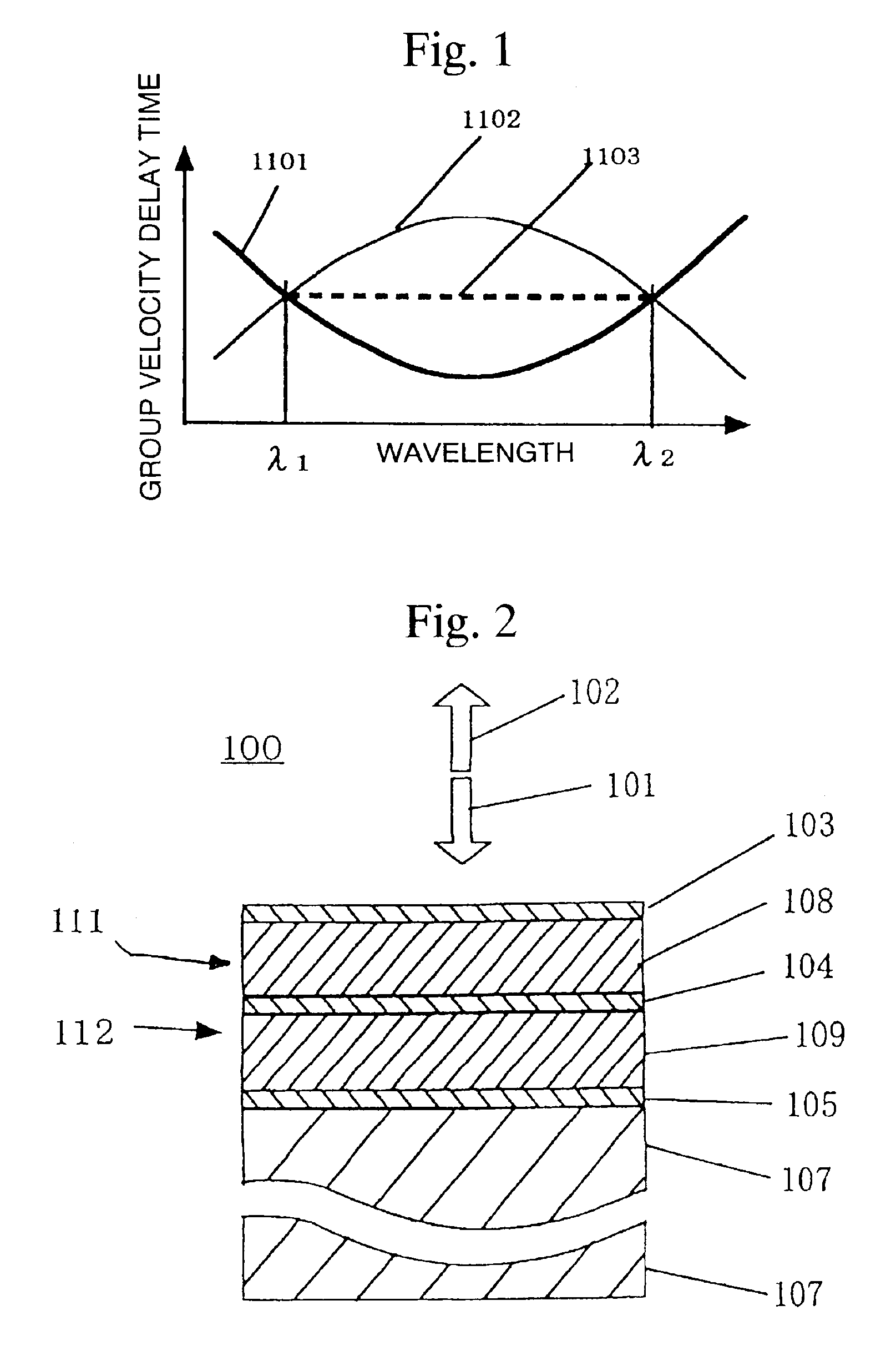
[0082]FIG. 1 is a drawing that explains a method for compensating dispersion occurring in communications using an optical fiber for the transmission path with an optical dispersion compensating element. Refere...


PUM


Abstract

An optical component of the present invention is compensated its optical dispersion, including third order dispersion, at low loss using optical dispersion compensating element comprising multi-layer film. In the optical component, an optical dispersion compensating element and a functional element are connected in series along an optical path.

Description

TECHNICAL FIELD[0001]The present invention relates to an optical component comprising an element such as wavelength selection filter compensated wavelength dispersion (hereinafter, also to simply be referred to as dispersion) and its dispersion compensation method. In the following explanation of the present invention, dispersion means wavelength dispersion, optical dispersion compensation is simply referred to as dispersion compensation, an optical dispersion compensating element is simply referred to as a dispersion compensating element, and optical dispersion compensation method is simply referred to as dispersion compensation method.[0002]The present invention relates to a dispersion compensating element comprising an element capable of compensating for dispersion of the second order or more (to be described later) occurring in a signal light through optical communications using an optical fiber for the transmission path (hereinafter, the element capable of compensating for disp...

Claims


Application Information

Patent Timeline
Patent Type & Authority Patents(United States)
IPC IPC(8): G02B27/10G02B5/28G02B6/13G02B6/12G02B6/132G02B6/34H04B10/18H04B10/2513
CPCG02B5/285G02B6/12007G02B6/132G02B6/29361G02B6/29394G02B27/142H04B10/25133
Inventor KIKUCHI, KAZUROTAKUSHIMA, YUICHIJABLONSKI, MARK KENNETHTANAKA, YUICHIKATAOKA, HARUKITOKITA, HIRONORIFURUKI, KENJIHIGASHI, NOBORUSATO, KAZUNARIYAMASHITA, SHIRO
Owner OYOKODEN LAB
Why Eureka
Try Eureka