Dispersion compensating method, dispersion compensating apparatus and optical transmission system

a technology of dispersion compensating applied in the field of dispersion compensating method, dispersion compensating apparatus and optical transmission system, to achieve the effect of reducing size and cos

Inactive Publication Date: 2005-03-22
FUJITSU LTD
View PDF16 Cites 50 Cited by
  • Summary
  • Abstract
  • Description
  • Claims
  • Application Information

AI Technical Summary

Benefits of technology

The present invention has been carried out in view of the conventional problems as described above, and it is therefore an object of the present invention to realize a dispersion compensating method capable of readily conducting automatic compensation of waveform degradation caused by dispersion characteristics of an optical transmission path, to thereby provide a dispersion compensating apparatus of reduced sizes at a reduced cost and an optical transmission system.

Problems solved by technology

Further, in case of applying an error-correcting code to the optical signal input via the optical transmission path, information concerning bit errors before error correction processing may be generated, or the number of bit errors at error correction processing may be detected.

Method used


Image

  • Dispersion compensating method, dispersion compensating apparatus and optical transmission system
  • Dispersion compensating method, dispersion compensating apparatus and optical transmission system
  • Dispersion compensating method, dispersion compensating apparatus and optical transmission system

Examples


first embodiment

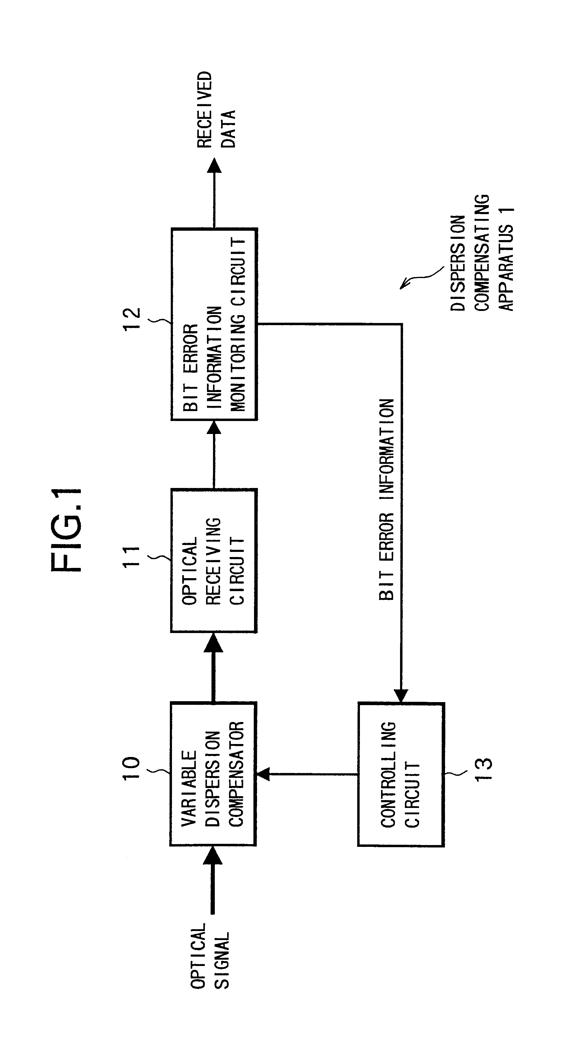
FIG. 7 is a block diagram showing a constitution of an optical transmission system according to the present invention.

This optical transmission system in FIG. 7 includes the dispersion compensating apparatus 1 of FIG. 1 in an optical receiver OR, concerning a system constitution for transmitting an optical signal sent from an optical sender OS to the optical receiver OR via an optical transmission path L. Like reference numerals as used for the aforementioned dispersion compensating apparatus 1 are used to denote identical elements, and the same rule applies corresponding to the following embodiments.

The optical sender OS is a known one for generating an optical signal of a single wavelength to transmit the optical signal to the optical transmission path L, in this embodiment. This optical sender OS includes a chirping generation circuit for applying chirping to the optical signal to be transmitted. Although not shown, the optical sender OS may be provided with a coder for applying ...

second embodiment

There will be described hereinafter an optical transmission system according to the present invention.

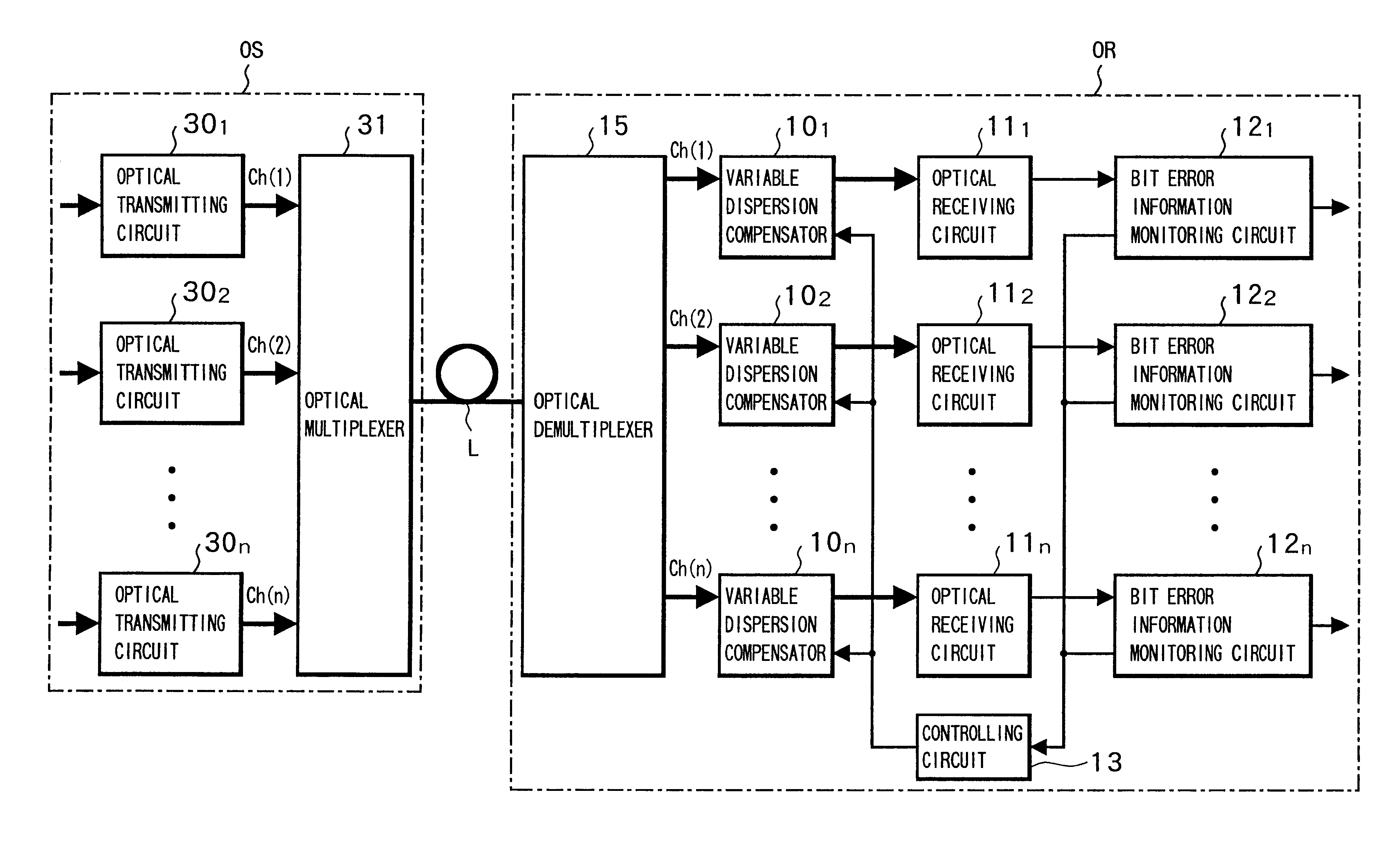
FIG. 9 is a block diagram showing a constitution of an optical transmission system according to the second embodiment of the present invention.

The optical transmission system of this embodiment in FIG. 9 is provided by applying the present invention to a so-called WDM optical transmission system in which the optical sender OS transmits, to the optical receiver OR, a wavelength division multiplexed (WDM) optical signal including a plurality of channel lights having different wavelengths from one another. Specifically, the optical sender OS includes: optical transmitting circuits 301, 302, . . . 30n corresponding to n wavelengths of channel lights, respectively; and an optical multiplexer 31 for multiplexing channel lights Ch(1) to Ch(n) at respective wavelengths output from the optical transmitting circuits 301, . . . 30n, to transmit multiplexed optical signal to the optical transmi...

third embodiment

There will be now described an optical transmission system according to the present invention.

FIG. 17 is a block diagram showing a constitution of an optical transmission system according to the third embodiment of the present invention.

In FIG. 17, this optical transmission system is constituted such that, in the system constitution of the second embodiment shown in FIG. 9, variable dispersion compensators 321, 322, . . . 32n are provided at the optical sender OS side, so as to correspond to the channel lights Ch(1) to Ch(n) and a controlling circuit 33 is provided for controlling the wavelength dispersion values of the respective variable dispersion compensator 321 to 32n. The constitution of the optical sender OS other than those described above, and the constitutions of the optical receiver OR and the optical transmission path L are identical with those of the second embodiment.

Similarly to the variable dispersion compensators 101 to 10n at the optical receiver OR side, the varia...


PUM


Abstract

The present invention aims at realizing a dispersion compensating method capable of readily conducting automatic compensation of waveform degradation caused by dispersion characteristics of an optical transmission path, and at providing a dispersion compensating apparatus and an optical transmission system, of a smaller size at a reduced cost. To this end, the dispersion compensating apparatus of the present invention comprises: a variable dispersion compensator for compensating for the dispersion of optical signal input via an optical transmission path; a bit error information monitoring circuit for generating bit error information of a received signal output from the variable dispersion compensator via an optical receiving circuit; and a controlling circuit for optimally controlling a wavelength dispersion value of the variable dispersion compensator based on the bit error information from the bit error information monitoring circuit.

Description

BACKGROUND OF THE INVENTION(1) Field of the InventionThe present invention relates to a dispersion compensating technique suitable for a long distance optical transmission system having a large capacity, and particularly to a dispersion compensating method, dispersion compensating apparatus and optical transmission system, which are capable of readily realizing automatic compensation of wavelength dispersion and polarization mode dispersion.(2) Related ArtRecently, there has been increased transmission speed of optical transmission apparatus such that an optical transmission apparatus of 10 Gb / s has been already practiced and an optical transmission system of 40 Gb / s is being developed. With the increased transmission speed, optical signal waveforms are considerably deteriorated due to wavelength dispersion characteristics of optical fibers and due to polarization mode dispersion characteristics of optical fibers and optical circuits, thereby resulting in a main factor which restric...

Claims


Application Information

Patent Timeline
Patent Type & Authority Patents(United States)
IPC IPC(8): H04B10/18H04B10/2507H04B10/07H04B10/2519H04B10/2525H04B10/2569
CPCH04B10/25133H04B10/25137H04J14/0221
Inventor NISHIMOTO, HIROSHIMIKAMI, SATOSHI
Owner FUJITSU LTD
Why Eureka
Try Eureka