Optical amplifier

a technology of optical amplifiers and amplifiers, applied in the field of optical amplifiers, can solve the problems of nonlinear optical limit, high optical power loss of dcfs and fbgs, and transmission line nonlinear effects,

Inactive Publication Date: 2001-05-22
HANGER SOLUTIONS LLC
View PDF1 Cites 54 Cited by
  • Summary
  • Abstract
  • Description
  • Claims
  • Application Information

AI Technical Summary

Problems solved by technology

On the other hand, when a WDM signal is transmitted over a transmission line, nonlinear optical effects will occur in the transmission line if the WDM signal is too powerful.
Both DCFs and FBGs have high optical power loss, however.
A DCF has a wide compensation wavelength bandwidth, but it also has a nonlinear optical limit.
In addition, the DCF 17 creates substantial signal transmission loss (optical power loss, approximately equal to several decibels), making it impossible for the optical amplifier 15 to generate high total output.
Specifically, high output is difficult to achieve with an optical amplifier 15 obtained using DCF.
With the conventional practice of amplifying the entire wavelength bandwidth of WDM signals by a single post-stage optical amplifier unit 13, however, inherent limitations are encountered when attempts are made to achieve high output and low optical output power difference across a broad wavelength band.
In the case of an FBG, however, the wavelength bandwidth within which the chromatic dispersion can be compensated for is narrow (for example, about 7 nm), limiting the bandwidth that can be transmitted by an optical amplifier when the FBG is introduced between the stages of the optical amplifier.

Method used


Image

  • Optical amplifier
  • Optical amplifier
  • Optical amplifier

Examples


first embodiment

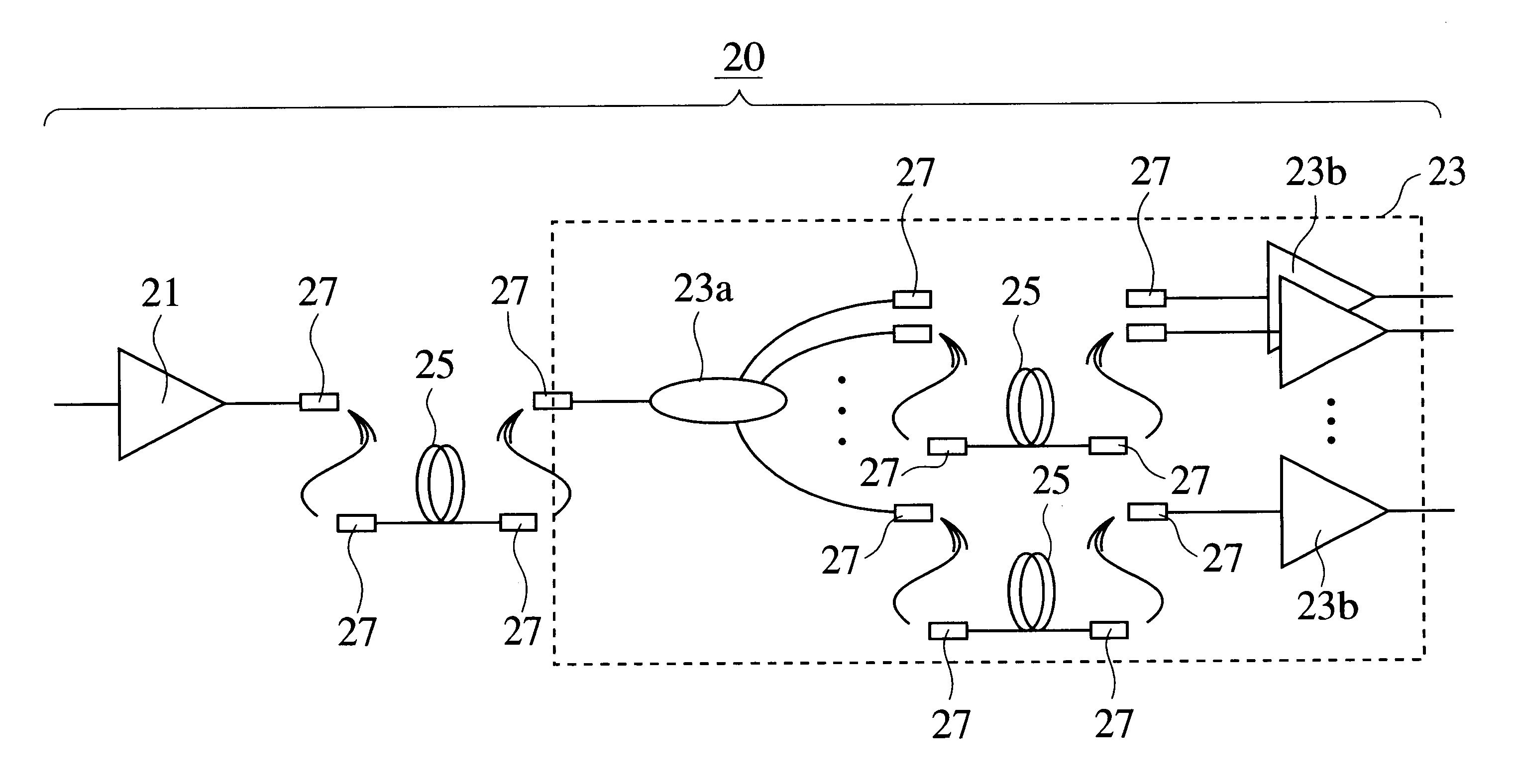
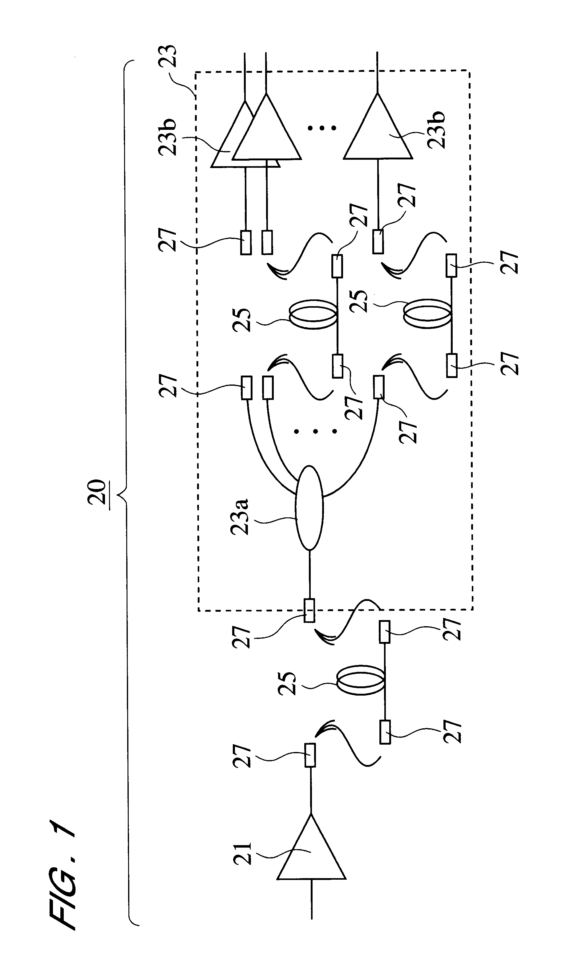
FIG. 1 is a diagram depicting the structure of the optical amplifier 20 of the first embodiment. The optical amplifier 20 of the first embodiment is an optical amplifier obtained by the cascade connection of two stages of optical amplifier units: a pre-stage optical amplifier unit 21 and a post-stage optical amplifier unit 23.

In the present invention, the post-stage optical amplifier unit 23 is configured as an optical amplifier unit comprising a first optical component 23a of a single input and N outputs that has an optical-demultiplexing or wavelength-division function, and N units of optical amplification means 23b provided in accordance with the N output terminals of the first optical component 23a. N is an arbitrary integer of 2 or greater.

The task of each of the N units of optical amplification means 23b is to amplify light or an optical signal that is output from the corresponding output terminals of the first optical component 23a.

In the configurational example depicted in F...

second embodiment

FIG. 4 is a diagram illustrating a configurational example of an optical amplifier 30 pertaining to a second embodiment. The optical amplifier 30 pertaining to the second aspect of the embodiment is different from the first aspect of the embodiment in that optical switches and a plurality of suboptical components (which correspond to second optical components) are used to form the required connections between the constituent elements depicted in FIG. 1, that is, between the optical components 21 and 23a, and / or 23a and 23b. Using optical switches allows connections between the required constituent elements to be made by selecting the desired suboptical components from among a plurality of suboptical components, and forming the connections by means of the selected suboptical components. In the optical amplifiers 201-204 of the above-described first embodiment (in which such optical switches are dispensed with), connections between the required constituent elements can only be made by...

third embodiment

The output characteristics of a WDM signal commonly exhibit a wavelength dependency when this signal is amplified with an EDFA. Specifically, an EDFA exhibits output characteristics that posses wavelength dependency output power difference.

When signal light that has wavelength dependency output power difference is amplified with a multistage EDFA, an S / N bias that depends on the wavelength is sometimes created and, in extreme cases, part of the signal is sometimes lost or another problem encountered.

In particular, the biggest problem with the optical output power difference is the increase in optical intensity in a specific wavelength band. To take optical amplification in the 1.5-.mu.m band as an example, optical intensity often increases near a wavelength of 1530 nm. As a result, light near the 1530-nm wavelength is intensified with multistage amplification.

Intensification of light near the 1530-nm wavelength enhances the pumping light consumed by the signals in this wavelength ba...


PUM


Abstract

There is provided an optical amplifier for reducing the optical output power difference and/or obtaining high output power across a wide wavelength band. The optical amplifier comprises a plurality of optical amplifier units connected in two or more stages. At least one of the optical amplifier units comprises a first optical component of a single input and N outputs that has an optical-demultiplexing function, and P units of optical amplification means for the individual amplification of light that is output from P (where 1<=P<=N) output terminals selected from the N (integer) output terminals of the first optical component. Second optical components are provided to the input side of the first optical component or between the output side of the first optical component and the input side of the optical amplification means. The second optical components are optical components having chromatic dispersion compensation functions, optical components having functions designed to compensate for wavelength dependency output power difference, or optical components demonstrating other required effects. The optical components are DCFs, FBGs, SMFs, optical filters, attenuators, or the like. The second optical components are provided nonselectively or selectively.

Description

1. Field of the InventionThe present invention relates to an optical amplifier designed to compensate for the optical power loss and / or wavelength dependency output power difference occurring during transmission of a WDM (Wavelength Division Multiplexing) signal.2. Description of Related ArtWhen a WDM signal is transmitted over long distances, optical amplifiers are introduced into transmission lines in order to compensate for the optical power loss in the transmission lines. Systems obtained by the multistage connection of optical amplifier units are often used as such optical amplifiers.On the other hand, when a WDM signal is transmitted over a transmission line, nonlinear optical effects will occur in the transmission line if the WDM signal is too powerful.DCFs (Dispersion compensating fibers) or FBGs (Fiber Bragg gratings) are commonly introduced into transmission lines in order to inhibit the formation of such nonlinear optical effects.Both DCFs and FBGs have high optical power...

Claims


Application Information

Patent Timeline
Patent Type & Authority Patents(United States)
IPC IPC(8): H01S3/067H04J14/02H01S3/06H04B10/17H01S3/23H04J14/00H04B10/2507H04B10/2519H04B10/2525H04B10/294
CPCH01S3/06754H04B10/294H04J14/0221H01S3/06758H01S3/2383H04B2210/258
Inventor SUZUKI, MIKIYANAKAMURA, TOSHIOSASAKI, AKIRASHIKII, SHIGERU
Owner HANGER SOLUTIONS LLC
Why Eureka
Try Eureka