Inverted write head for vertical recording

Inactive Publication Date: 2005-09-13
HEADWAY TECH INC
View PDF13 Cites 2 Cited by
  • Summary
  • Abstract
  • Description
  • Claims
  • Application Information

AI Technical Summary

Benefits of technology

[0011]Yet another object has been that said improved read-write head have increased immunity to interference from the write flux.
[0012]A still further object has been that, while still meeting the above objectives, said improved read-write head has a good vertical write field profile.
[0013]These objects have been achieved by providing the read head with shields that are limited to performing only shielding and do not share other magnetic functions with parts of the write head. This

Problems solved by technology

Although micro jag can be utilized to cope with this o

Method used


Image

  • Inverted write head for vertical recording
  • Inverted write head for vertical recording
  • Inverted write head for vertical recording

Examples


Example

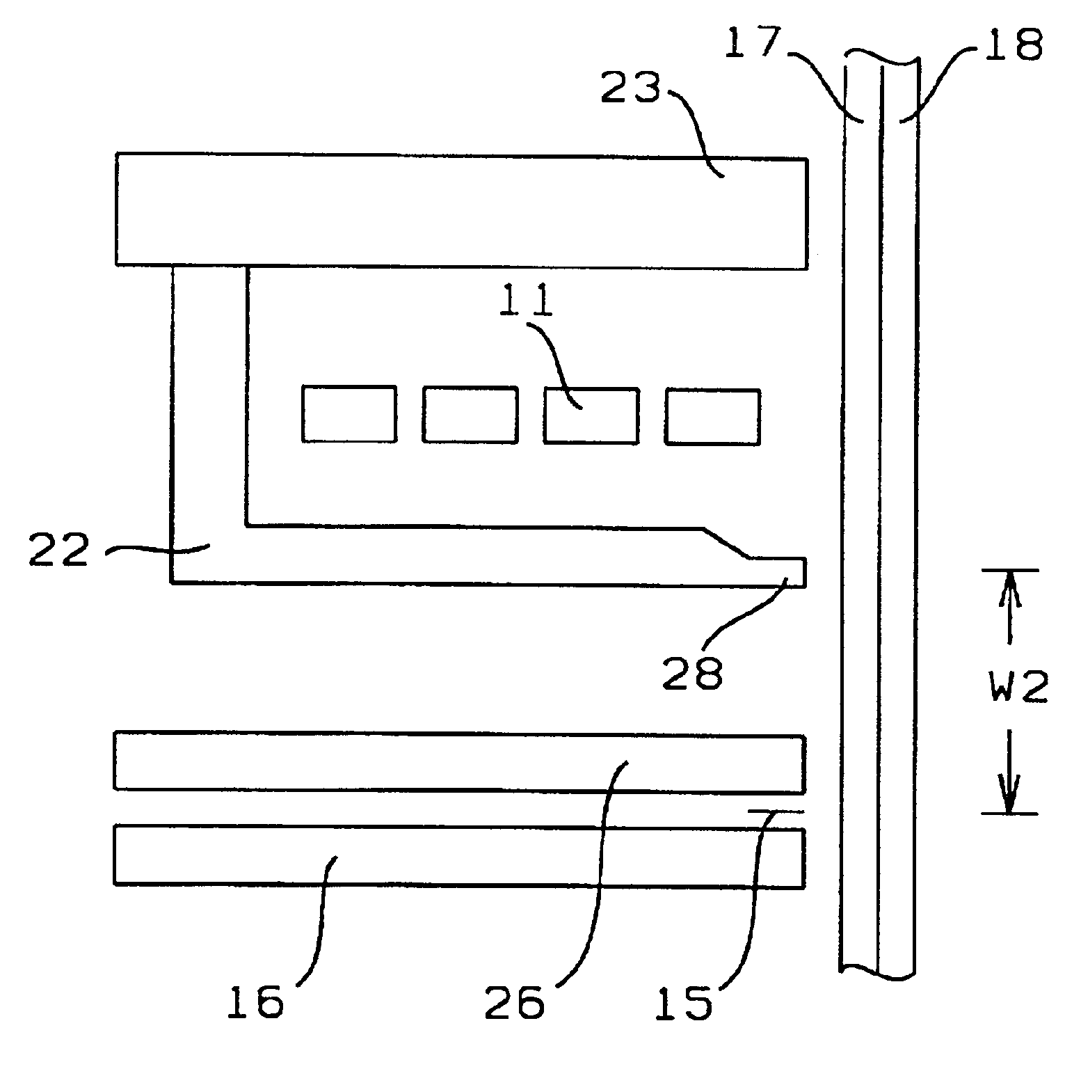
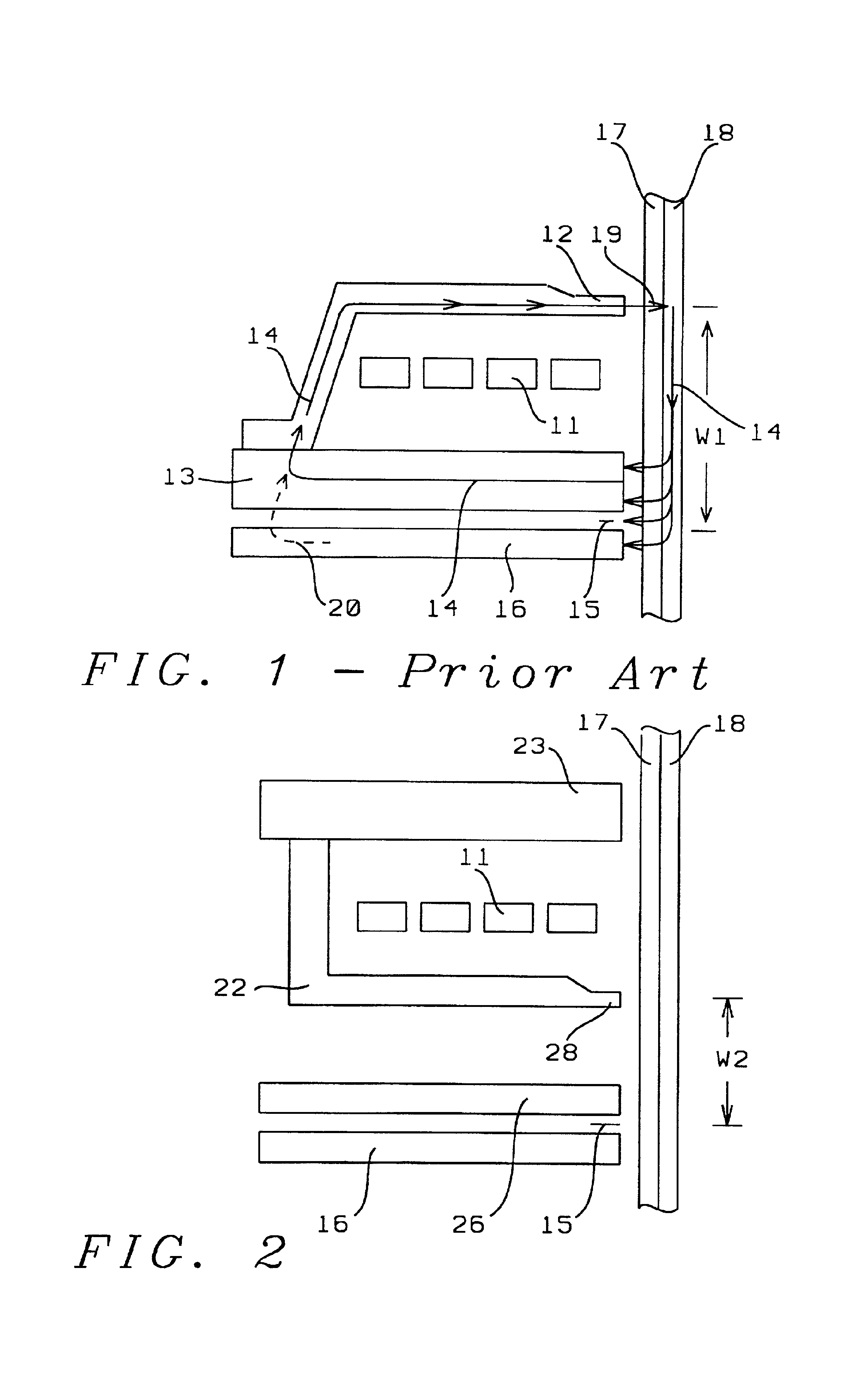
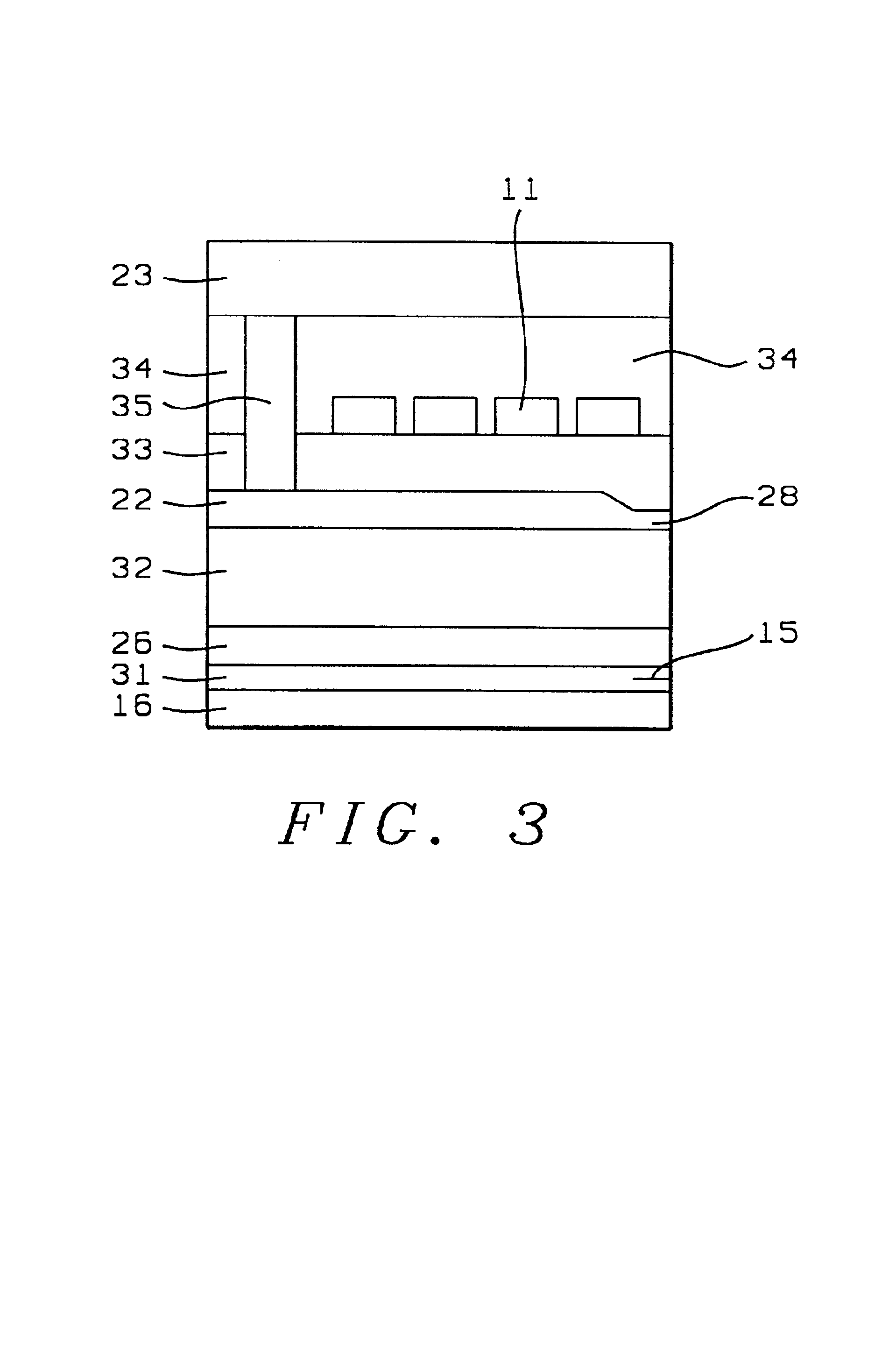
[0017]Referring now to FIG. 2, we show there the magnetic read-write structure of the present invention. The key difference between the present invention and the prior art is that the flux return pole of the write-head has been moved to the top and is no longer shared with the upper read-head shield. General features of the structure include read head 15 which lies between two magnetic shields 16 and 26, the latter being dedicated to serving as a shield and not being shared by any other part of the structure.

[0018]The write head for perpendicular magnetic recording includes write pole 22 and a flux return pole 23. Because 2 and 23 form a complete flux closure through disk keeper layer 18, no magnetic flux due to the writing operation can escape and pass through the read head shields 16 and 26. This design allows the read-to-write head separation W2 to be kept to less than about 4 microns. The distance W2 is limited by the need to maintain a good vertical write field profile at tip 2...


PUM


Abstract

An improved read-write head for use with magnetic disks is described. This improvement has been achieved by providing the read head with shields that are limited to performing only shielding and do not share other magnetic functions with parts of the write head. This allows the write pole to be located very close to the read head since the top shield is no longer required to provide a flux return path, this function now being provided by a separate return flux pole. The separation between the read and write heads is now limited only by the need to achieve an optimum vertical field profile. Two key advantages of this structure are a substantial reduction in the jagging distance of the system and a reduced interference field from the write flux.

Description

FIELD OF THE INVENTION[0001]The invention relates to the general field of magnetic recording with particular reference to very high density recording on magnetic disks.BACKGROUND OF THE INVENTION[0002]Vertical recording has long been considered for use in ultra-high density storage applications. 200 G bits per square inch is considered feasible for such a design. In its application, the transducer consists of a reader such as a spin valve (SV), magnetic tunneling junction (MTJ) and current perpendicular to plane (CPP), giant magneto-resistance (GMR) device, and a writer, typically a single pole construction, as illustrated in FIG. 1. Write coil 11 is encapsulated between upper write pole 12 and shared pole 13, with the latter providing a flux return path for the write flux 14. As can be seen, the magnetic flux in region 19 is perpendicular to recording layer 17 with the magnetic circuit being completed inside keeper layer 18.[0003]The read portion of the device consists of the read ...

Claims


Application Information

Patent Timeline
IPC IPC(8): G11B5/265G11B5/127G11B5/10G11B5/012G11B5/115G11B5/48G11B5/00G11B5/39G11B5/31
CPCB82Y10/00B82Y25/00G11B5/012G11B5/115G11B5/1278G11B5/2652G11B5/3909G11B5/4886G11B5/3903G11B2005/0029G11B2005/3996
Inventor LIN, CHARLES
Owner HEADWAY TECH INC
Why Eureka
Try Eureka