However, the prior art Ethernet switches and some other electronic devices do not meet these standards.
This is extremely undesirable since it could result in corruption of real-time
mission critical control messages being transmitted over the network via the switch.
Moreover, actual damage to the switch itself is possible if
high voltage electrical transients are directly coupled into the device via the
copper cables overcoming the limited
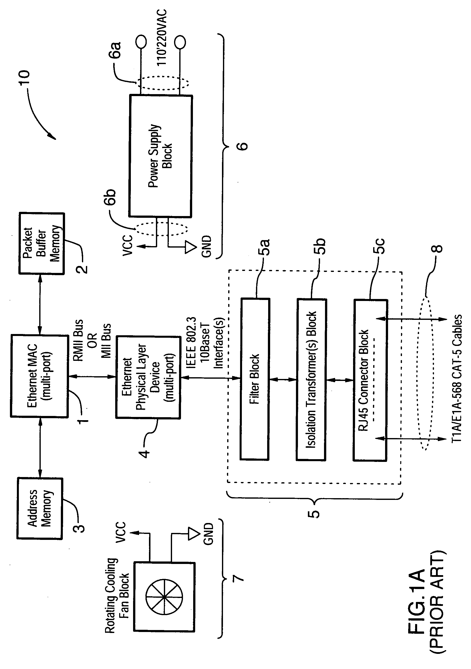
electrical isolation (typically 1000V to 1500V RMS) provided by isolation transformers 5b.
This is not a requirement for commercial grade Ethernet Switches and thus the power supply inputs 6a do not provide suitable transient suppression circuitry.
Furthermore, commercial grade Ethernet switches are not specifically designed to withstand EMI (
Electromagnetic Interference) levels of 35V / m as specified by ANSI / IEEE C37.90.2 (1995) which is typical of many substation environments.
Accordingly, conventional circuit 10 suffers from the
disadvantage that it is susceptible to electrical transients and electromagnetic interference at levels which are possible, or even common, in utility substation environment.
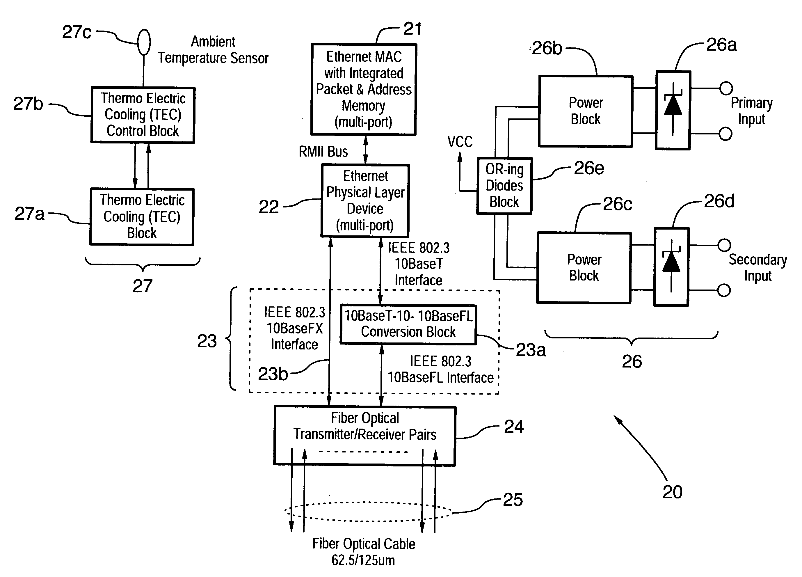
The design of FIG. 1A is also susceptible to mechanical breakdown because of the use of rotating cooling fan 7 required to cool the electronic components.
However, the
operating temperature range for devices in the substation environment such as protective relays is specified by the IEC 60255-6 (1998) standard as −25° C. to +55° C. Therefore, not only is the circuit 10 of FIG. 1A susceptible to failure, it also does not meet the requirements of the environmental conditions which are possible, or even common, in utility substation environments.
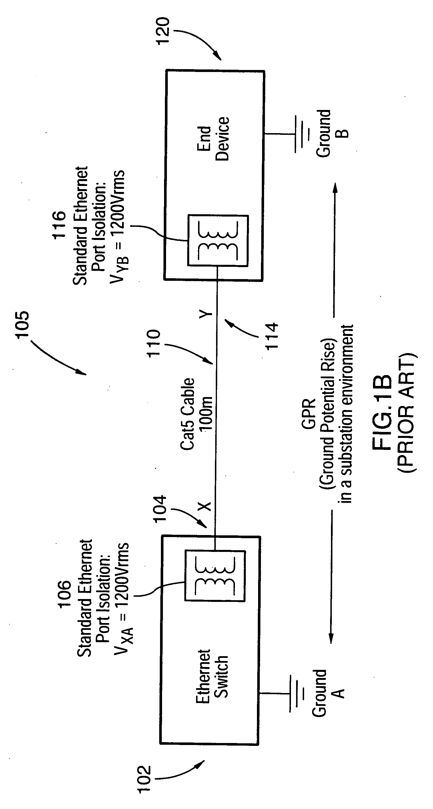
One potential communication equipment fault which may arise, particularly in, but not exclusively in
electric utility substations, includes a ground potential rise (GPR).
Because the Ethernet switches and other IEDs may be located in a network that covers a large area, a ground potential rise within one location may have catastrophic effects to the components in that area and / or the components in other areas.
For instance, any equipment with
copper wire connections across the location of the ground potential rise, such as, for example, an Ethernet switching hub located in the
control room connecting to a
protective relay device or intelligent switch gear device in a switch
yard, will experience high levels of ground potential rise which can damage the equipment by causing the galvanic isolation barriers between the two connected devices, such as the Ethernet switch in the
control room and the
protective relay in the switch
yard, to break down.
In this way, the internal components of the
electronics could be exposed to high voltages and currents causing potential physical damage.
For communication equipment
interfacing using electrical connections such as by
copper wire, or a combination of electrical connections and fibre optical media, and / or a single
electrical connection using
copper wire or other conductive material, any ground potential rise presents a serious concern.
It is also apparent that such damage could occur at a
critical time, thereby damaging the overall network precisely when communication is most critical.

