
Endless belt for electrophotographic device

a technology of electrophotography and endless belts, which is applied in the direction of electrographic processes, instruments, synthetic resin layered products, etc., can solve the problems of inability to perform a uniform velocity motion of recording medium, failure of elastic layer to exhibit desired physical properties, and inorganic filler and other additives have a risk of failure to achieve the desired physical properties of elastic layers, improve flexibility and wear resistance, and reduce manufacturing costs

Inactive Publication Date: 2012-02-09
SUMITOMO RIKO CO LTD
View PDF7 Cites 6 Cited by
  • Summary
  • Abstract
  • Description
  • Claims
  • Application Information

AI Technical Summary

Benefits of technology

[0010]The present invention has been made in the light of the situations described above. It is therefore an object of the present invention to provide an endless belt for an electrophotographic device, which has an elastic layer formed on a surface of a base layer and including a large content of an inorganic filler, and which has high degrees of flexibility and wear resistance in its surface portion (in its elastic layer).
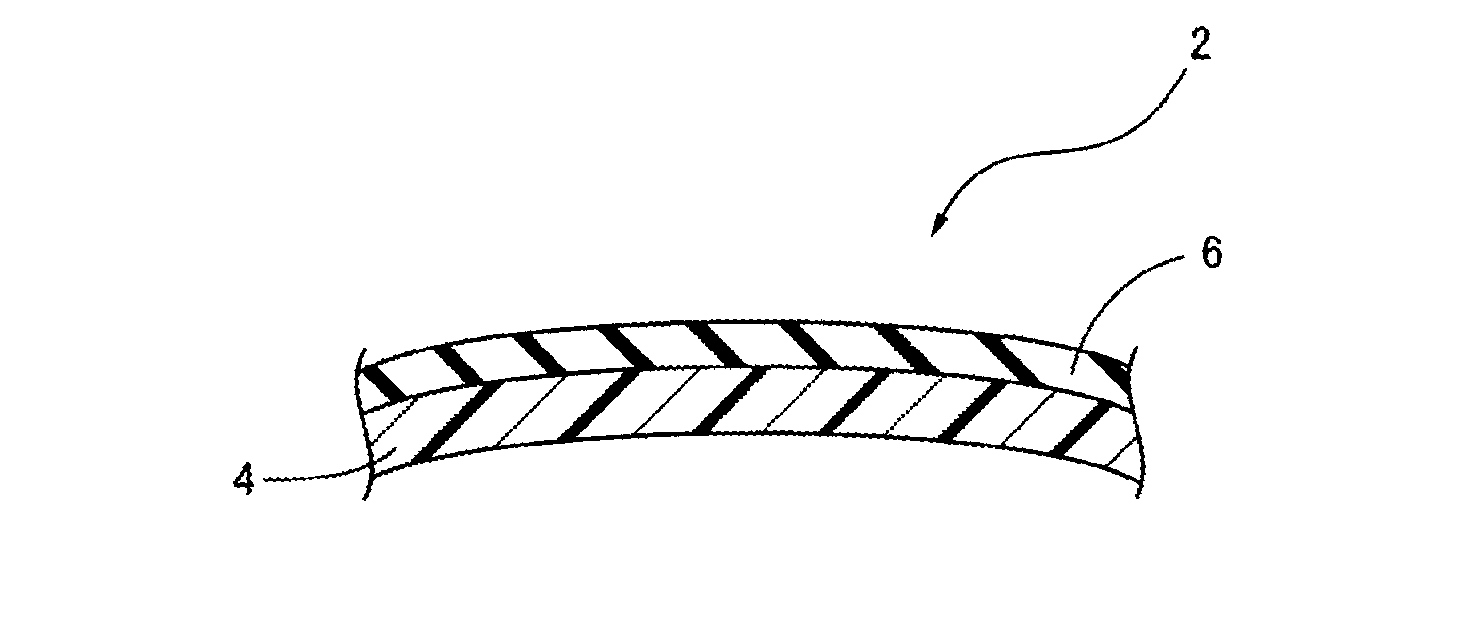
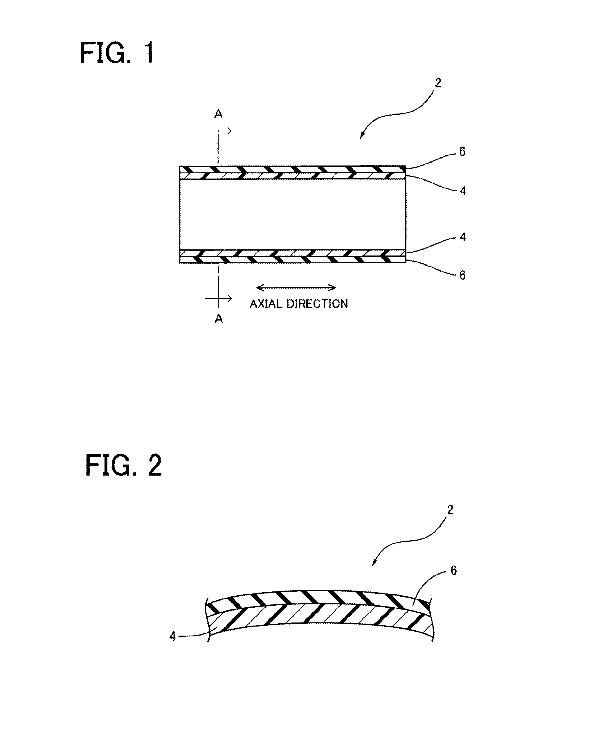
[0019]The endless belt for the electrophotographic device of the present invention described above comprises the base layer, and the elastic layer which is formed on a surface of the base layer, by using the rubber composition including at least one rubber material and at least one inorganic filler, and which is characterized by 1) 40-75% by mass of a total organic component, and 2) the product of the indentation Young's modulus (MPa) α and the fracture strain (%) β which is within the range of 6000-50000. The endless belt of this invention provides various advantages owing to the inclusion of the at least one inorganic filler to the elastic layer, more specifically, not only improvements of formability and fire resistance, and reduction of the cost of manufacture, but also improvements of flexibility and wear resistance in a surface portion of the elastic layer, permitting the use of the endless belt as an intermediate image transfer belt of the electrophotographic device for a long period of time, while effectively preventing superficial wearing or removal of the elastic layer in its local areas corresponding to the edge or end portions of a recording medium (such as a sheet of paper) to which an image is transferred from the intermediate image transfer belt, whereby the endless belt is given a longer service life as compared with the conventional endless belt.

Problems solved by technology

Although this configuration assures a sufficiently high quality of the image transferred to the recording medium, the electrophotographic device still suffers from a potential problem of a failure to perform a uniform velocity motion of the recording medium.
However, the endless belts having the elastic layer containing the inorganic filler and other additives have a risk of failure of the elastic layer to exhibit desired physical properties (desired flexibility, in particular), if the contents of the additives (inorganic filler, in particular) in the elastic layer are excessively large.
Described in detail, the endless belts the elastic layer of which has an excessively large content of the inorganic filler have a low degree of flexibility, giving rise to a risk of failure to assure a desired transfer of the toner image, and a risk of a superficial removal of the elastic layer due to friction between the surface of the elastic layer and the recording medium (paper sheet) or a belt cleaning member, when used for a long period of time as the intermediate image transfer belt in the electrophotographic device.
However, an extensive study by the present inventors of the endless belts disclosed in those patent documents and other conventional endless belts reveals that the endless belts having the elastic layer which is formed on the base layer and which has a large content of the inorganic filler, in particular, do not really have a sufficiently high degree of wear resistance in their surface portion (in the surface portion of their elastic layer).

Method used


Image

  • Endless belt for electrophotographic device
  • Endless belt for electrophotographic device
  • Endless belt for electrophotographic device

Examples


examples

[0066]Some examples of this invention will be described to further clarify the present invention. However, it is to be understood that the present invention is not limited to the details of these illustrated example, and that the invention may be embodied with various changes, modifications or improvements, which may occur to those skilled in the art, without departing from the spirit of this invention.

—Preparation of Base Layer Material—

[0067]Initially, RIKACOAT EN-20 (trade name) available from New Japan Chemical Co., Ltd. was provided as a polyimide resin (PI), and VYLOMAX HR-16NN (trade name) available from Toyobo Co., Ltd. was provided as a polyamideimide resin (PAI). Then, 100 parts by weight of each of the polyimide resin and polyamideimide resin, and 10 parts by weight of carbon black were added to and mixed with 800 parts by weight of N-methyl-2-pyrrolidone (NMP), to prepare two kinds of the liquid base layer material. “PI” and “PAI” in Tables 1-3 below respectively represe...


PUM

PropertyMeasurementUnit
Fracture strainaaaaaaaaaa
Percent by massaaaaaaaaaa
Pressureaaaaaaaaaa

Abstract

An endless belt for an electrophotographic device having high degrees of flexibility and wear resistance in a surface portion of the elastic layer is provided. The endless belt for an electrophotographic device, includes a base layer, and an elastic layer which is formed on a surface of the base layer, by using a rubber composition including at least one rubber material and at least one inorganic filler in which the elastic layer has 40-75% by mass of a total organic component, and a product P of an indentation Young's modulus (MPa) α and a fracture strain (%) β that is within a range of 6000-50000.

Description

[0001]The present application is based on Japanese Patent Application No. 2010-177758 filed Aug. 6, 2010, the contents of which are incorporated herein by reference.BACKGROUND OF THE INVENTION[0002]1. Field of the Invention[0003]The present invention relates to an endless belt for an electrophotographic device, and more particularly to an intermediate image transfer belt or other endless belt suitably usable for a full-color LBP (laser beam printer), a full-color PPC (plane paper copier) or other electrophotographic device which utilizes an electrophotographic technology.[0004]2. Description of Related Art[0005]In a conventional full-color LBP, a full-color PPC or other electrophotographic device utilizing an electrophotographic technology, an electrically conductive endless belt (seamless belt) is used for various purposes. For example, an intermediate image transfer belt is widely known as an endless belt for an electrophotographic device wherein a toner image formed on a photosen...

Claims


Application Information

Patent Timeline
IPC IPC(8): B32B27/08C08L9/02C08L9/06C08L11/00C08L23/22
CPCG03G15/162Y10T428/31721
Inventor KIMPARA, TERUYOSHINATSUME, SHINICHIKANDA, SHIGEKIFUJITA, TSUKASAENDO, SATOSHI
Owner SUMITOMO RIKO CO LTD
Learn More