Data holding apparatus and data read out method

a data holding device and data technology, applied in the direction of digital storage, pulse techniques, instruments, etc., can solve the problems of data loss, previous data cannot be restored, and data loss is large,

Inactive Publication Date: 2005-09-13
ROHM CO LTD
View PDF5 Cites 47 Cited by
  • Summary
  • Abstract
  • Description
  • Claims
  • Application Information

AI Technical Summary

Benefits of technology

[0018]The method for reading data, according to the present invention, is one, using a data holding device having a data storing circuit for releasing an amount of electric charge commensurate with stored data to an electric charge releasing node when a reading signal is given; a data restoring circuit for restoring contents of the data stored in the data storing circuit on the basis of a voltage produced at the electric charge releasing node with the released electric charge; and a field effect transistor having a drain region connected substantially to the electric charge releasing node and having a junction with its joining direction from the drain region to a base semiconductor region of the field effect transistor in agreement with a direction of the electric charge released; the method comprising: starting to give a voltage substantially the same as a source voltage that is to be given to a source region of the field effect transistor, to the base semiconductor region either simultaneously with or before giving a reading signal to the data storing circuit; and giving the source voltage to the source region after giving the reading signal, to the data storing circuit.

Problems solved by technology

Such a data holding circuit, however, usually can hold data only in volatile manner, and so the data are lost when power supply is stopped.
That is to say, even if the power supply is resumed, the previous data cannot be restored.
In the case the sequential process is interrupted due to power failure or the like, the process must be redone from scratch, incurring much loss of time.
Therefore, if the frequency of the clock pulse CK is high, it is hard to accurately latch the input data D. This makes it hard to use such a circuit in devices that are required to function at high speeds.
In other words, detection margin when data are restored by resuming power supply is small and so the reliability of restored data is low.

Method used


Image

  • Data holding apparatus and data read out method
  • Data holding apparatus and data read out method
  • Data holding apparatus and data read out method

Examples


Embodiment Construction

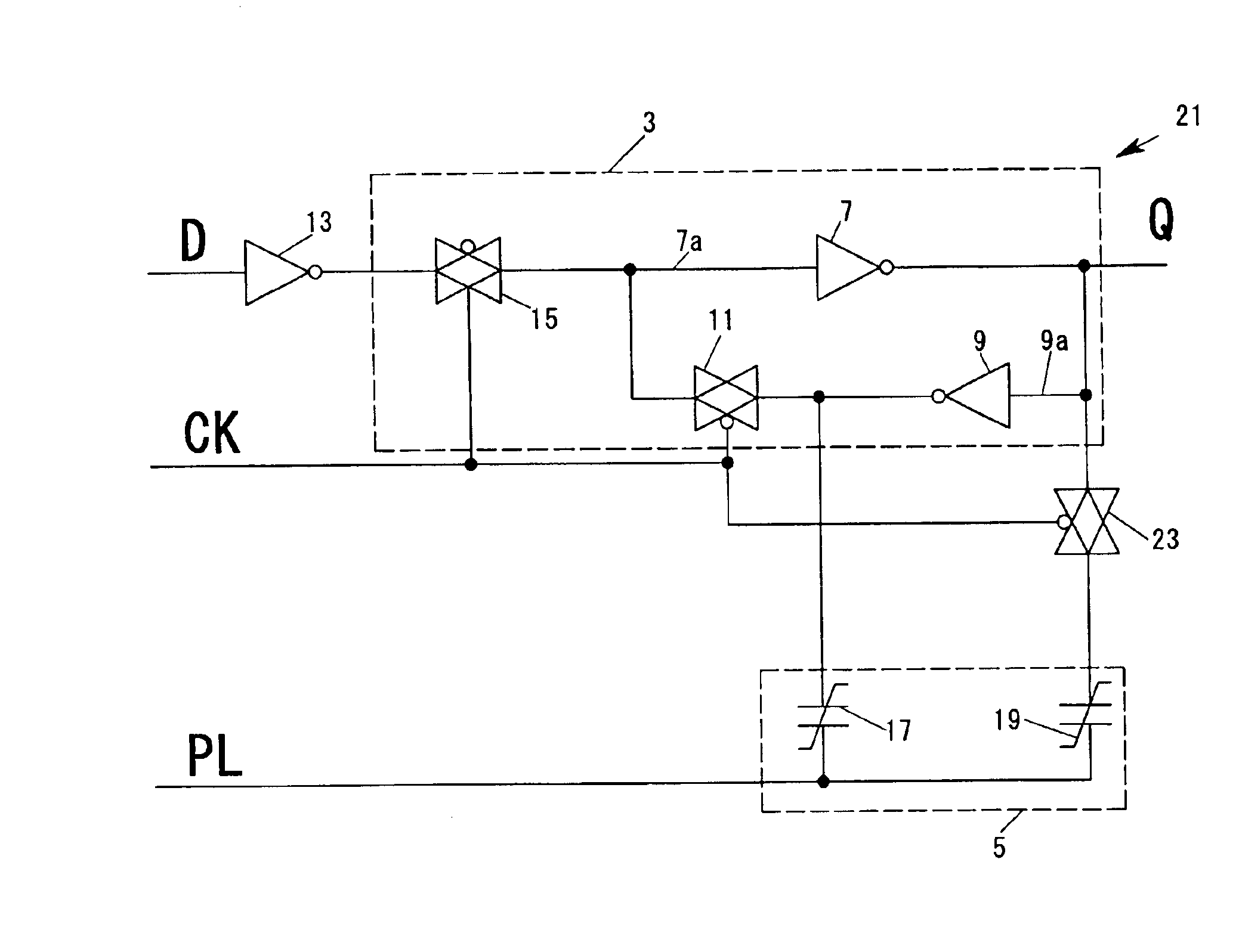
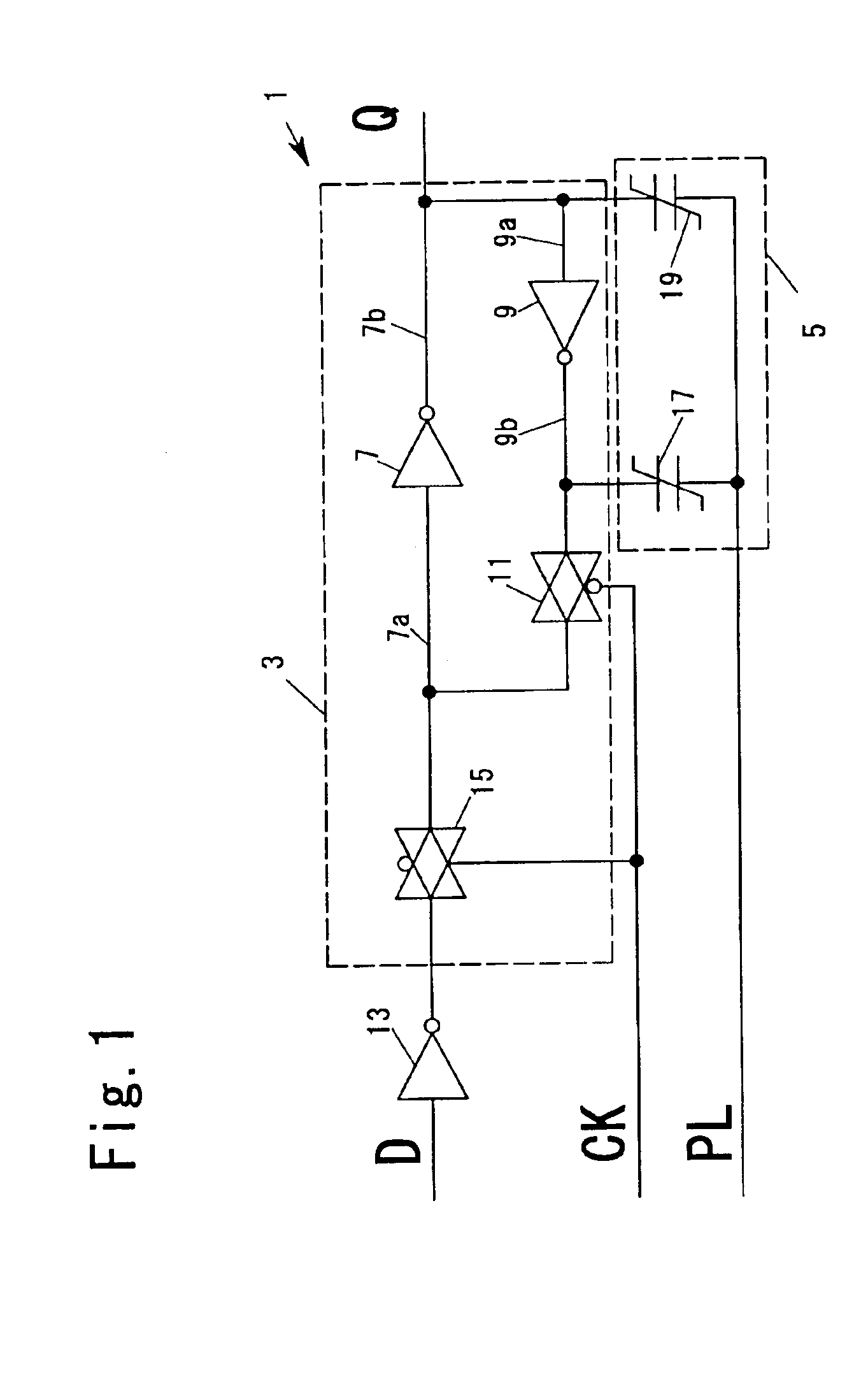
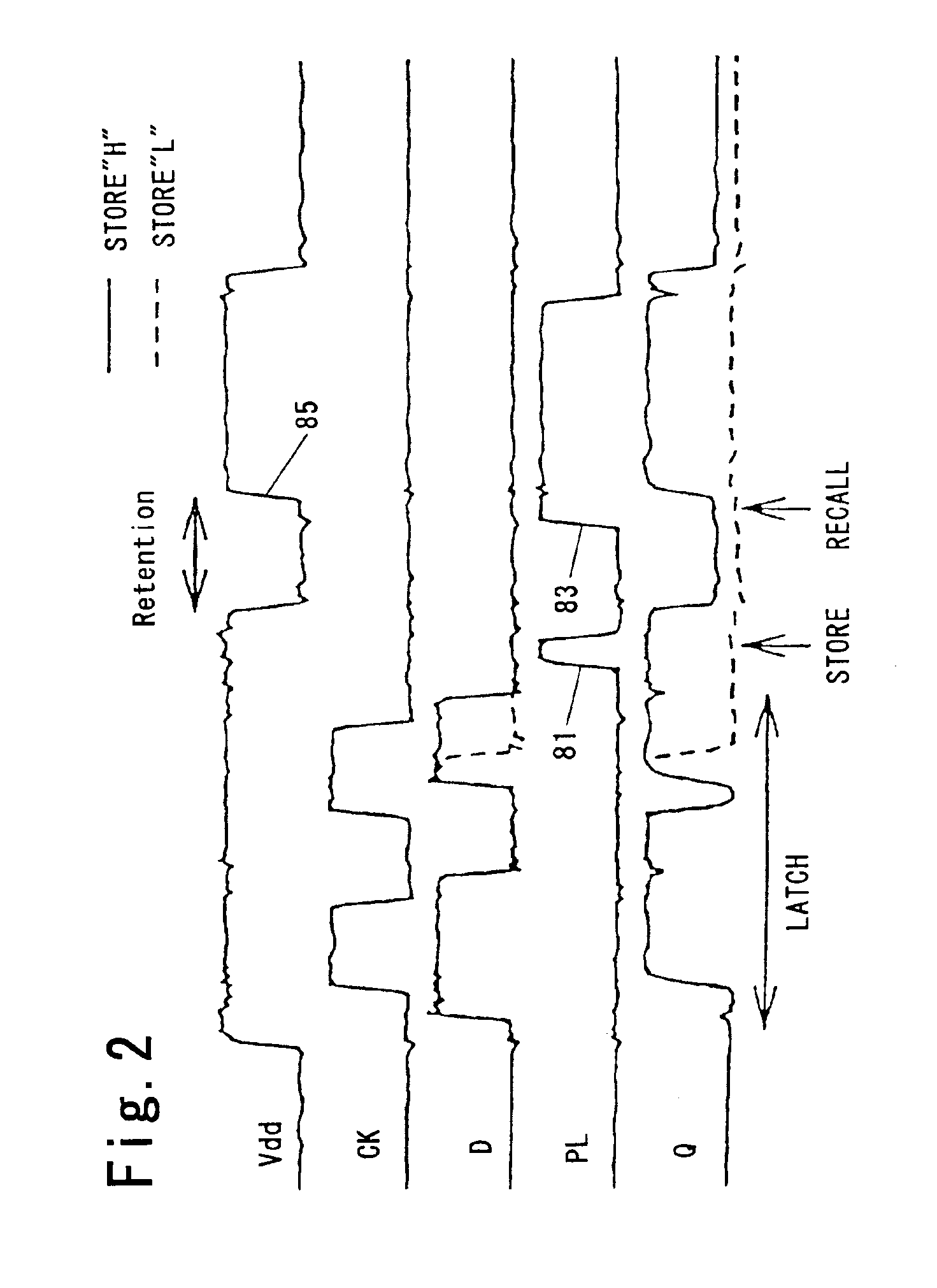
[0033]FIG. 1 is a circuit diagram of a data holding device 1 as a first embodiment of the present invention. The data holding device 1 comprises a data latch circuit 3 as a data holding circuit and a ferroelectric storage section 5.

[0034]The data latch circuit 3 has a pair of inverter circuits 7 and 9 that can be interconnected to form a series loop. The output node 9b of the inverter circuit 9 disposed in the feedback path is connected to the input node 7a of the inverter circuit 7 disposed in the main signal path through the first on-off gate, a transfer gate 11.

[0035]The transfer gate 11 is controlled with clock pulses CK given to a clock signal line CK. That is to say, the transfer gate 11 is on-off-controlled with the clock pulses CK to be on when holding data and to be off when passing data. The output node 7b of the inverter circuit 7 is directly connected to the input node 9a of the inverter circuit 9.

[0036]In this embodiment, the transfer gate is made up of an n-MOSFET (n-M...


PUM


Abstract

A data holding device is provided that is capable of holding data even if the power supply is shut off and reliability in holding data is high. The data holding device 1 is provided with a data latch circuit 3 and a ferroelectric memory section 5. Ferroelectric capacitors 17 and 19 are capable of storing data in non-volatile manner. One end of the ferroelectric capacitor 17 is connected to the input node 7a of an inverter circuit 7 through a transfer gate 11. The transfer gate 11 is in the off state when data are passed. Therefore, even if input data D changes when data are passed, the change is quickly transmitted to the input node 7a, so that reliability of latching operation does not lower even if the operation is made at usual speeds.

Description

CROSS-REFERENCE TO RELATED APPLICATIONS[0001]The entire disclosure of a Japanese patent application No. 2001-353848 filed on Nov. 19, 2001 including its specification, claims, drawings, and summary is incorporated herein by reference.TECHNICAL FIELD[0002]The present invention relates to a data holding device and a data reading method.BACKGROUND ART[0003]As a data holding circuit for use in the sequential circuit such as the latch circuit, a circuit made by for example connecting two inverter circuits in a series loop is known. Such a data holding circuit, however, usually can hold data only in volatile manner, and so the data are lost when power supply is stopped. That is to say, even if the power supply is resumed, the previous data cannot be restored.[0004]Therefore, for example when a sequential process using such a sequential circuit must be suspended for any reason, the power supply must be maintained to hold the data. Accordingly electric power is consumed. In the case the seq...

Claims


Application Information

Patent Timeline
Patent Type & Authority Patents(United States)
IPC IPC(8): G11C14/00H03K3/037H03K3/00G11C8/02
CPCG11C14/00G11C14/0072H03K3/0375
Inventor FUJIMORI, YOSHIKAZU
Owner ROHM CO LTD
Why Eureka
Try Eureka