
State information and routing table updates in large scale data networks

a technology of state information and routing table, applied in the field of communication network monitoring, can solve problems such as oscillation, violent variation of end-to-end traffic carried by the network, and harm to the network

Inactive Publication Date: 2005-09-13
RPX CLEARINGHOUSE
View PDF5 Cites 101 Cited by
  • Summary
  • Abstract
  • Description
  • Claims
  • Application Information

AI Technical Summary

Benefits of technology

"The present invention provides a network control method and apparatus for a large-scale network with numerous nodes. The network controller is operable to determine the primary network controller for each node and to communicate with other network controllers. The network controller is also operable to generate a plurality of routes from each node to another node and to rank the routes based on their cost. The invention also provides a method of determining the route set of a given node based on the route sets of other nodes and the inverse route sets of linked nodes. The technical effects of the invention include improved network control and efficient route selection for large networks."

Problems solved by technology

Any routing of traffic on the basis of fast varying traffic occupancy state information must be done with great caution since it can lead to harmful network oscillations where the end-to-end traffic carried by the network varies violently.
Oscillation can occur due to large propagation delays between a point of observation or measurement and a point of control.
This process is not always easy to implement in a wide-coverage network with potentially long propagation delays.
It is also undesirable that traffic occupancy information be disseminated across the network when the propagation delay is significant.
Flooding may lead to excessive transfer of redundant information.
Although the information redundancy may be reduced to some extent by using a hierarchical structure for the purpose of information dissemination and routing decisions, flooding becomes awkward when the number of links per node increases.
Performing routing table computations in response to every link state change limits the scalability of a network.

Method used


Image

  • State information and routing table updates in large scale data networks
  • State information and routing table updates in large scale data networks
  • State information and routing table updates in large scale data networks

Examples


Embodiment Construction

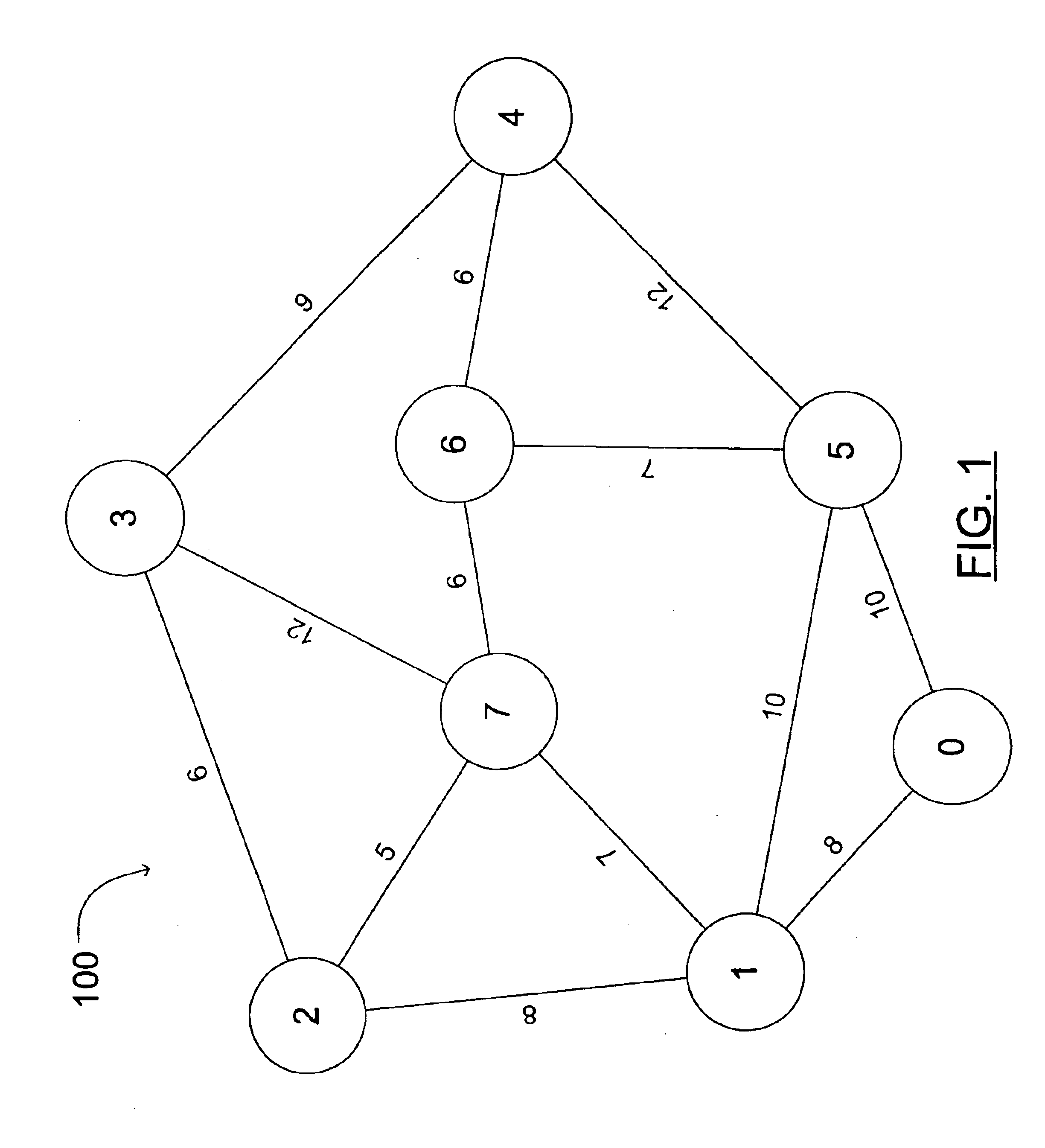
[0044]FIG. 1 models a communication system as a graph 100 of nodes and links between the nodes, each link between a pair of nodes is shown to have an associated metric, in this case, a cost of the link. Each link shown in graph 100 actually represents two unidirectional links, one unidirectional link for each of the opposite directions. The link metrics shown are chosen to be equal in the opposite directions for convenience of presentation. In general, the opposite link metrics need not be equal.

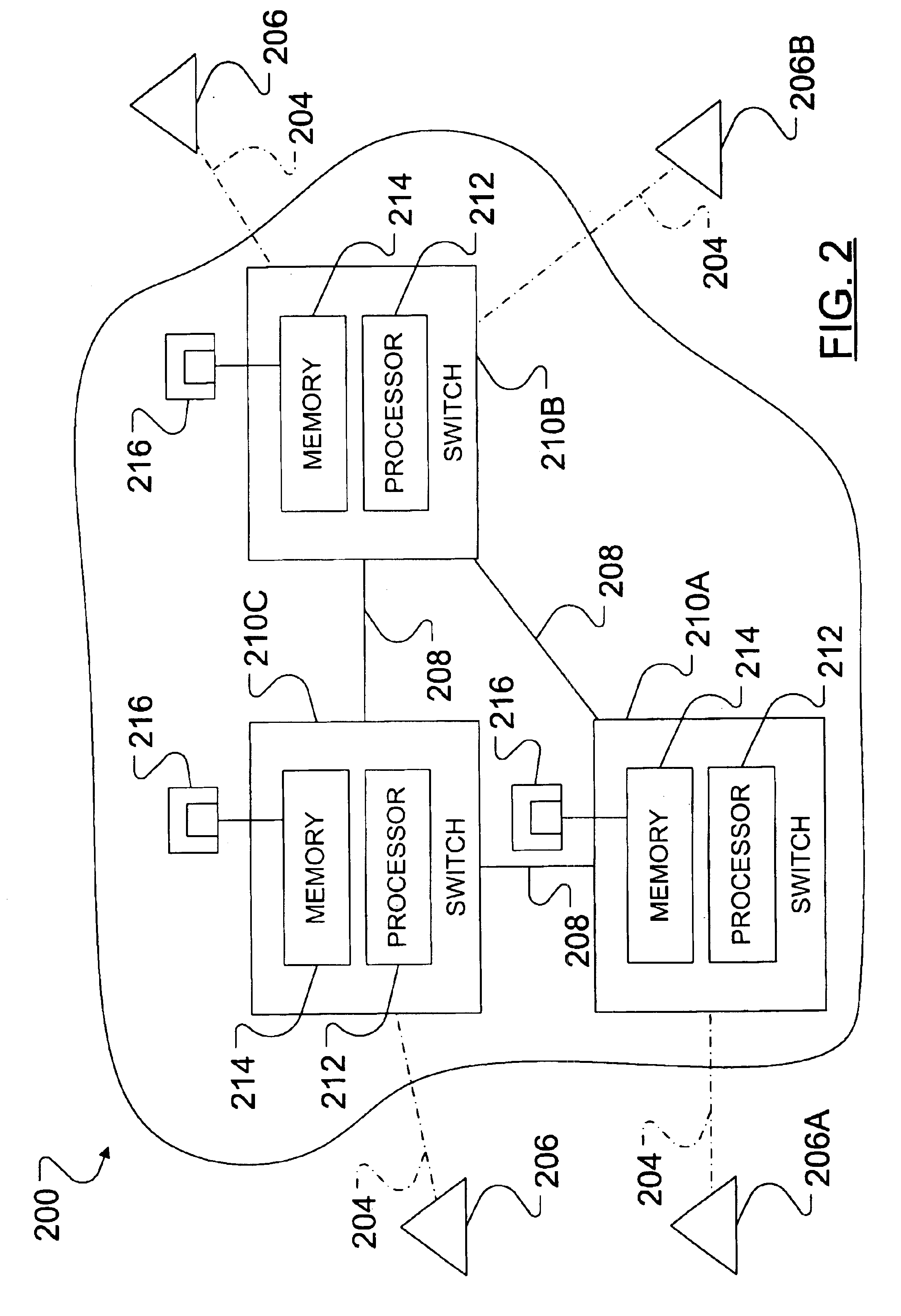
[0045]FIG. 2 illustrates a network suitable for use with this invention. Network 200 comprises a number of nodes 210 which are nodes interconnected by links 208. A number of traffic sources and traffic sinks (work stations, servers) 206 are connected to the nodes 210 by local links 204. Each node comprises a processor 212 and a memory 214 loaded with route selection software for executing the method of this invention from software medium 216 which could be a disk, a tape, a chip or a random ...


PUM


Abstract

In a communication network comprising nodes and links between the nodes, a controller node disseminates link state information. A nodal routing table exists at each node comprising routes between pairs of nodes. The nodal routing table is either populated by the given node based on network information received from the controlling node or populated at the controlling node and received by the given node. Each node receives heartbeat signals from its neighbouring nodes. An unexpected delay between heartbeat signals may be perceived as a failure of a link. The perceived failure of that link is reported by the perceiving node to the controlling node. Upon receiving link failure information from a node, the controlling node may determine a subset of nodes in the network influenced by the link failure and indicate the link failure to the determined subset of influenced nodes.

Description

CROSS-REFERENCE TO RELATED APPLICATIONS[0001]This application is a continuation of U.S. patent application Ser. No. 09 / 405,003, filed Sep. 27, 1999 now U.S. Pat. No. 6,744,775.GOVERNMENT LICENSE RIGHTS[0002]This invention was made with Government support under Technology Investment Agreement F30602-98-2-0194 awarded by the Air Force. The Government has certain rights in the invention.FIELD OF THE INVENTION[0003]The present invention relates to monitoring of communication networks and more particularly to state information and routing table updates in large scale data networks.BACKGROUND OF THE INVENTION[0004]In a network which comprises nodes and links between the nodes, a node is generally capable of switching connection based traffic, such as in a telephone network or an ATM (asynchronous transfer mode) network, or connectionless traffic, such as in the Internet. In a connection based network, a node may function as a switch whereas, in a connectionless network, a node may functio...

Claims


Application Information

Patent Timeline
Patent Type & Authority Patents(United States)
IPC IPC(8): H04L12/56H04L12/28H04L45/02H04L45/24H04L45/28H04L45/42H04L45/74
CPCH04L45/02H04L45/025H04L45/22H04L12/28H04L45/42H04L45/54H04L45/28H04L12/26H04L43/00H04L45/03
Inventor BESHAI, MAGED E.VICKERS, RICHARD
Owner RPX CLEARINGHOUSE
Learn More