Reflected or transmitted light scanner and image processing method for scanned-in image samples

a technology scanner, which is applied in the field of reflected or transmitted light scanner and image processing method for scanned-in image samples, can solve the problems of intensive density fluctuation and typical local very limited, and achieve the effect of small expenditure of resources and fast defect correction

Inactive Publication Date: 2005-09-13
AGFAPHOTO
View PDF10 Cites 13 Cited by
  • Summary
  • Abstract
  • Description
  • Claims
  • Application Information

AI Technical Summary

Benefits of technology

[0008]Thus, it is the principal objective of the present invention to design a reflected or transmitted light scanner and an image processing method such that very fast defect correction can be ensured with a consistent image quality with small expenditures in resources.

Problems solved by technology

Thus, it is typically a locally very limited but intensive density fluctuation.

Method used


Image

  • Reflected or transmitted light scanner and image processing method for scanned-in image samples
  • Reflected or transmitted light scanner and image processing method for scanned-in image samples
  • Reflected or transmitted light scanner and image processing method for scanned-in image samples

Examples


Embodiment Construction

[0033]The preferred embodiments of the present invention will now be described with reference to FIGS. 1-3 of the drawings.

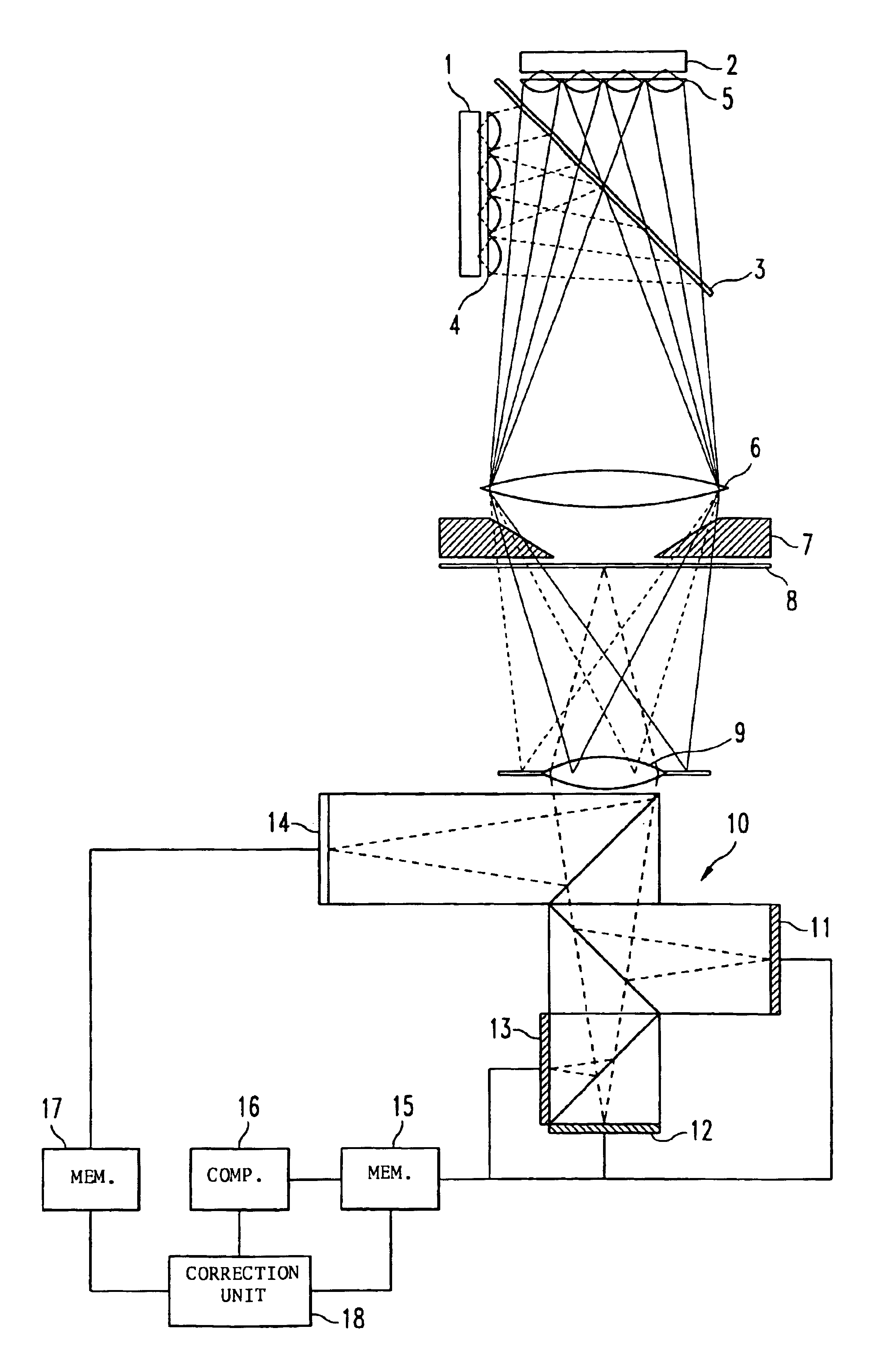
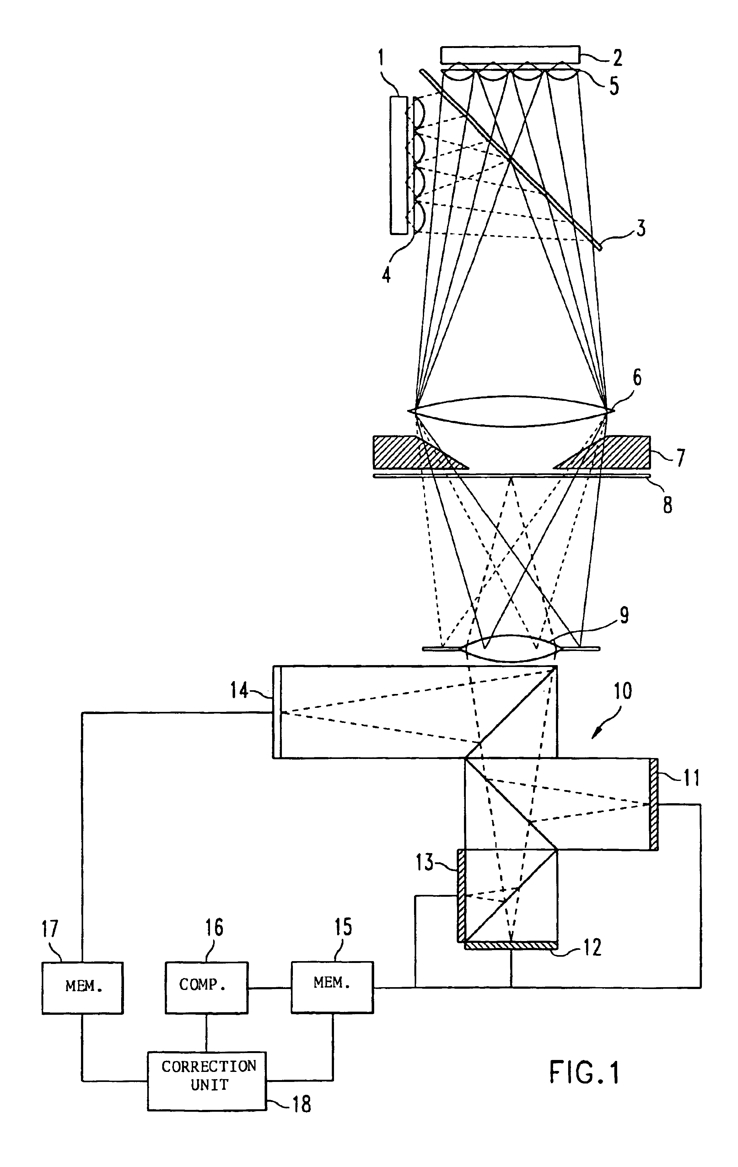
[0034]FIG. 1 schematically presents the design of an exemplary embodiment of a transmitted light scanner according to the invention. Two multi-colored LED arrays 1 and 2, whose light paths are combined using a beam splitter 3, are used as illumination devices. For example, LED array 1 is made up of red and green LEDs, whose light is focused using a lens array 4 arranged in series. LED array 2, on the other hand, includes infrared and blue LEDs whose light is focused as well, using a lens array 5 arranged in series, and then guided to the beam splitter 3. The multi-colored light that is combined at the dichroic beam splitter 3 is guided through the mask of the film stage 7 to the image sample 8 using a condenser lens 6. The multi-colored light penetrating the film stage 7 is focused by a reproducing lens 9 onto a beam splitter prism complex 10, from where it is r...


PUM


Abstract

A reflected or transmitted light scanner includes an illumination device for illuminating image material, a carrier for holding the image material, and a recording device for recording the light transmitted through the image material and for pixel by pixel conversion of the light into electric signals that can be used to generate original image signals in several colors as well as a defect signal. The reflected or transmitted light scanner further comprises a memory device for storing the image and defect signals, pixel by pixel; a computing device for generating low-pass signals from the image signals; a memory device for storing the low-pass signals, pixel by pixel; and a correction device for selecting between the image signal and the low-pass signal, or a combination of image signal and low-pass signal, for each pixel, in dependence upon the value or the position of the defect signal for the respective pixel.

Description

BACKGROUND OF THE INVENTION[0001]The invention relates to a reflected or transmitted light scanner and an image processing method for scanned-in image samples.[0002]When scanning image samples, the scanned images often exhibit defects that may have various causes. A potential cause for the defective areas may be image light dispersed on scratches of the sample. Other potential causes are dust or other particles present on the sample or on the image recording device, or errors in the imaging optics or the recording device.[0003]Several methods have already been recommended to correct these types of defects in the image.[0004]U.S. Pat. No. 4,680,638 describes a method that uses an infrared scan for correcting defects for a video film. The defect that is detected using the infrared scan is corrected either by replacing the image information with information of a previous image of the film, or through interpolation of the defective area. However, replacing the defective image area with ...

Claims


Application Information

Patent Timeline
Patent Type & Authority Patents(United States)
IPC IPC(8): H04N1/409H04N1/56H04N1/58
CPCH04N1/4097H04N1/58
Inventor GROSCHUP, THOMASSCHUHRKE, THOMAS
Owner AGFAPHOTO
Why Eureka
Try Eureka