Transport system with tunable channel spacing DWDM

a technology of optical transport and channel spacing, applied in the field of optical transport systems, can solve the problems of limiting consumer and business access to the bandwidth of the various transmission media used to transport information, hardware used cannot allow channel spacing to be varied, and each channel in the dwdm system can only accommodate bit rates, so as to reduce fiber waste

Inactive Publication Date: 2005-09-13
FUJITSU LTD
View PDF19 Cites 21 Cited by
  • Summary
  • Abstract
  • Description
  • Claims
  • Application Information

AI Technical Summary

Benefits of technology

[0004]Fiber optic transport systems is one of the promising technologies for increasing data transmission speeds and capacity. Fiber optic lines have many advantages over other media, and relatively recent gains make future use of this technology very attractive to both the buyers and sellers of bandwidth.
[0018]The disclosed innovations, in various embodiments, provide one or more of at least the following advantages:

Problems solved by technology

However, the bandwidth of the various transmission media used to transport information limits consumer and business access.
All current DWDM transport systems are designed with fixed channel spacings, meaning the hardware used does not allow channel spacings to be varied.
Each emitter operates on a single channel, and the filters are of fixed bandwidth, which means that each channel in the DWDM system can only accommodate bit rates that require no more bandwidth than that channel's filter can pass.
If more information is attempted to be modulated onto a channel than that channel is designed to carry, the bandwidth after modulation would be too great to pass the filters.
Because the channels are of fixed spacing, the total bandwidth may not be used efficiently in many situations.
This causes the smaller spectrum transmission to occupy unnecessary bandwidth in the DWDM system.
This results in unnecessarily unused bandwidth.
Another circumstance where fixed channel spacing wastes bandwidth occurs when there is sufficient unused bandwidth on the fiber to accommodate a high bit rate signal, but that unused bandwidth is already distributed among several fixed, lower bit rate channels.
In this case, the high bit rate signal may not be transmitted, and fiber capacity is wasted.

Method used


Image

  • Transport system with tunable channel spacing DWDM
  • Transport system with tunable channel spacing DWDM
  • Transport system with tunable channel spacing DWDM

Examples


Embodiment Construction

[0034]The numerous innovative teachings of the present application will be described with particular reference to the presently preferred embodiment (by way of example, and not of limitation).

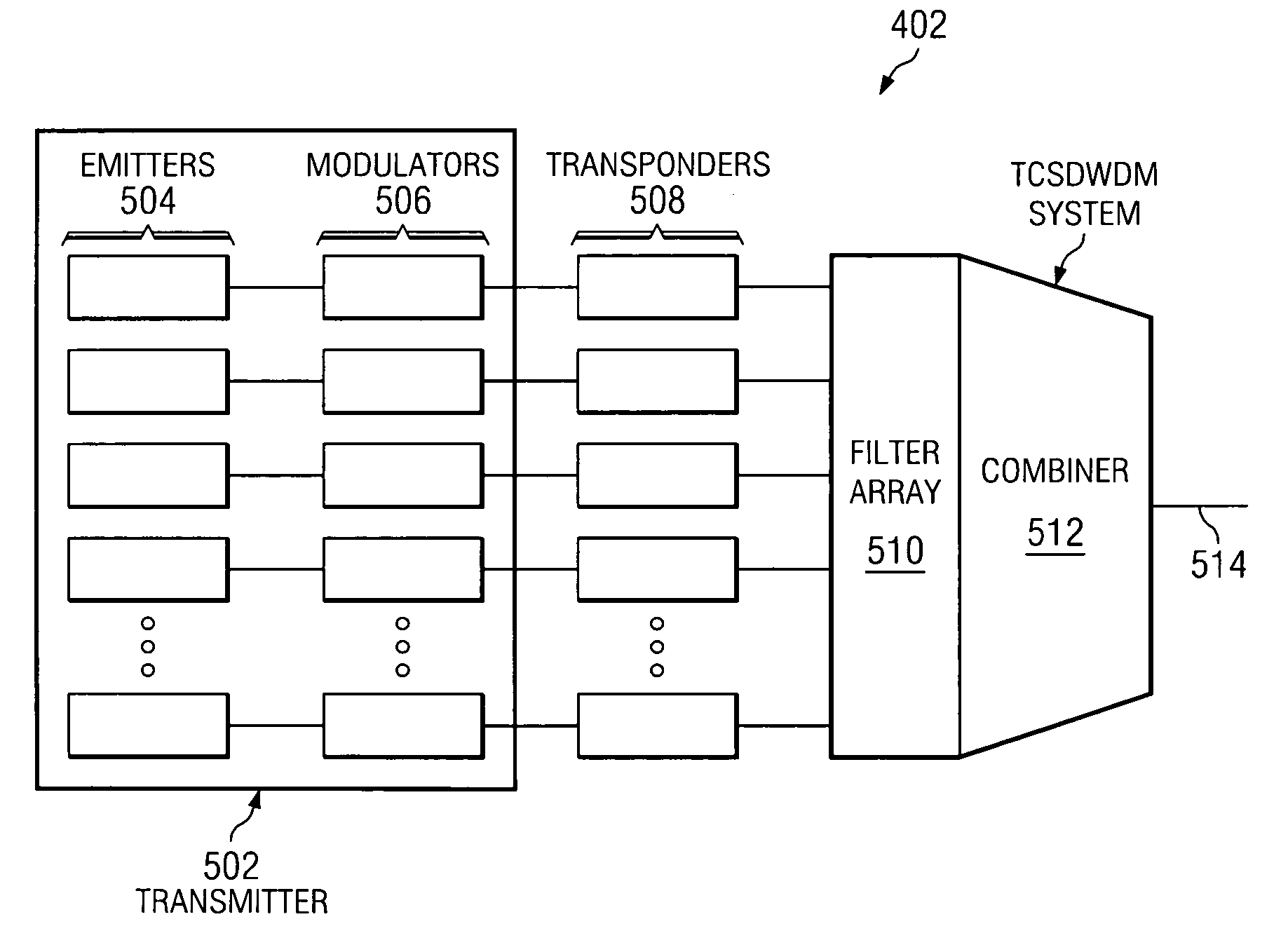
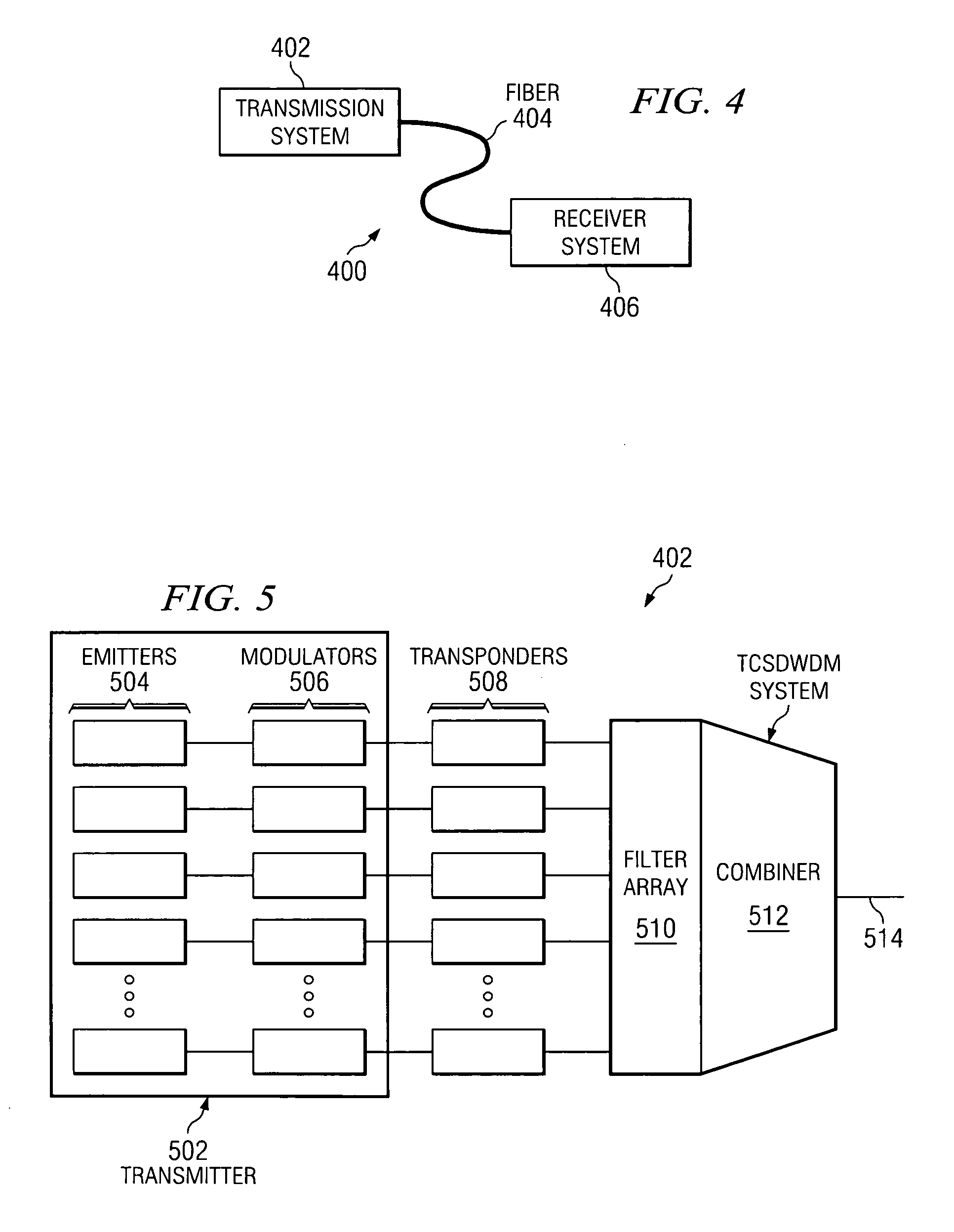
[0035]The optical transport system 400 of the preferred embodiment consists of a transmission system 402, a transmission medium 404, and a receiver system 406, as shown in FIG. 4. The transmission system 402, detailed in FIG. 5, includes the transmitter 502 consisting of several emitters 504 each emitting a carrier signal tuned to a channel central wavelength. This signal is intensity modulated, for instance, by a Mach-Zender interferometer. The modulation alters the intensity of the carrier signal by constructive and destructive interference through the interferometer to encode the information signal onto the carrier, so that after modulation the emitted light contains the data to be transmitted. Modulating more data onto a channel increases the bandwidth requirement for that channel. For exam...


PUM


Abstract

An optical transport system that uses tunable filters to vary the central wavelengths and spectrum widths of channels within the system to more efficiently use the bandwidth of the fiber. Higher bit rate channels may be divided into multiple lower bit rate channels, and lower bit rate channels may be combined to form higher bit rate channels.

Description

BACKGROUND AND SUMMARY OF THE INVENTION[0001]The present invention relates to optical transport systems, and more particularly to dense wavelength division multiplexing (DWDM) optical transport systems.[0002]Background: Optical Transport Systems[0003]Consumer and business demand for data transmission capability has increased beyond all expectations with the introduction of the internet. Now, consumers may tap into an information base that literally spans the globe and contains more data than any other single information source. The internet also allows users access to music, video, and other entertainment. Likewise, businesses are now interconnected to a degree previously unheard of. However, the bandwidth of the various transmission media used to transport information limits consumer and business access. Government and industry regulation of airwaves combined with technological limits in data transmission has fostered innovation in telecommunications seeking to expand transmission ...

Claims


Application Information

Patent Timeline
Patent Type & Authority Patents(United States)
IPC IPC(8): H04J14/02H04B10/155H04B10/152
CPCH04B10/50H04J14/02H04J14/0227H04J14/0246H04J14/0279
Inventor WAY, DAVID G.
Owner FUJITSU LTD
Why Eureka
Try Eureka