
System and method for facilitating context-switching in a multi-context computer system

a computer system and context-switching technology, applied in computing, instruments, electric digital data processing, etc., can solve problems such as known systems failing to meet one or more requirements

Inactive Publication Date: 2005-09-13
VMWARE INC
View PDF25 Cites 193 Cited by
  • Summary
  • Abstract
  • Description
  • Claims
  • Application Information

AI Technical Summary

Benefits of technology

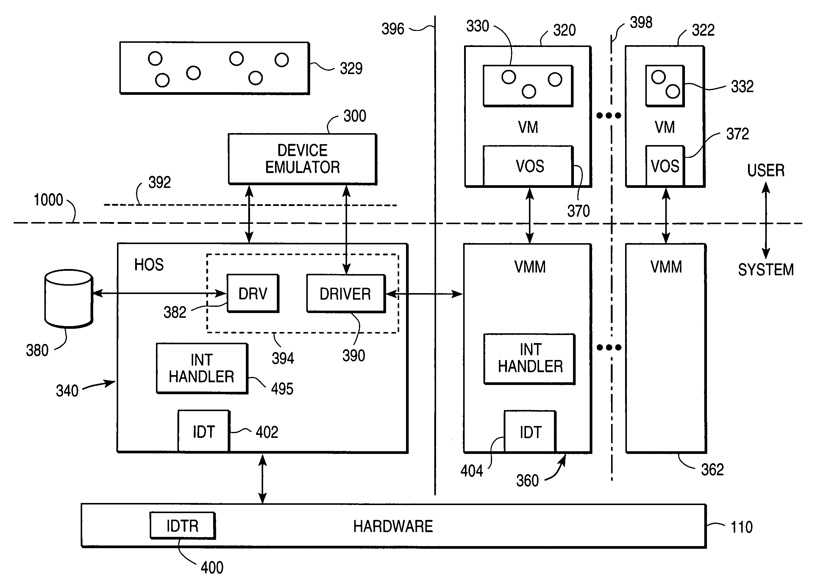
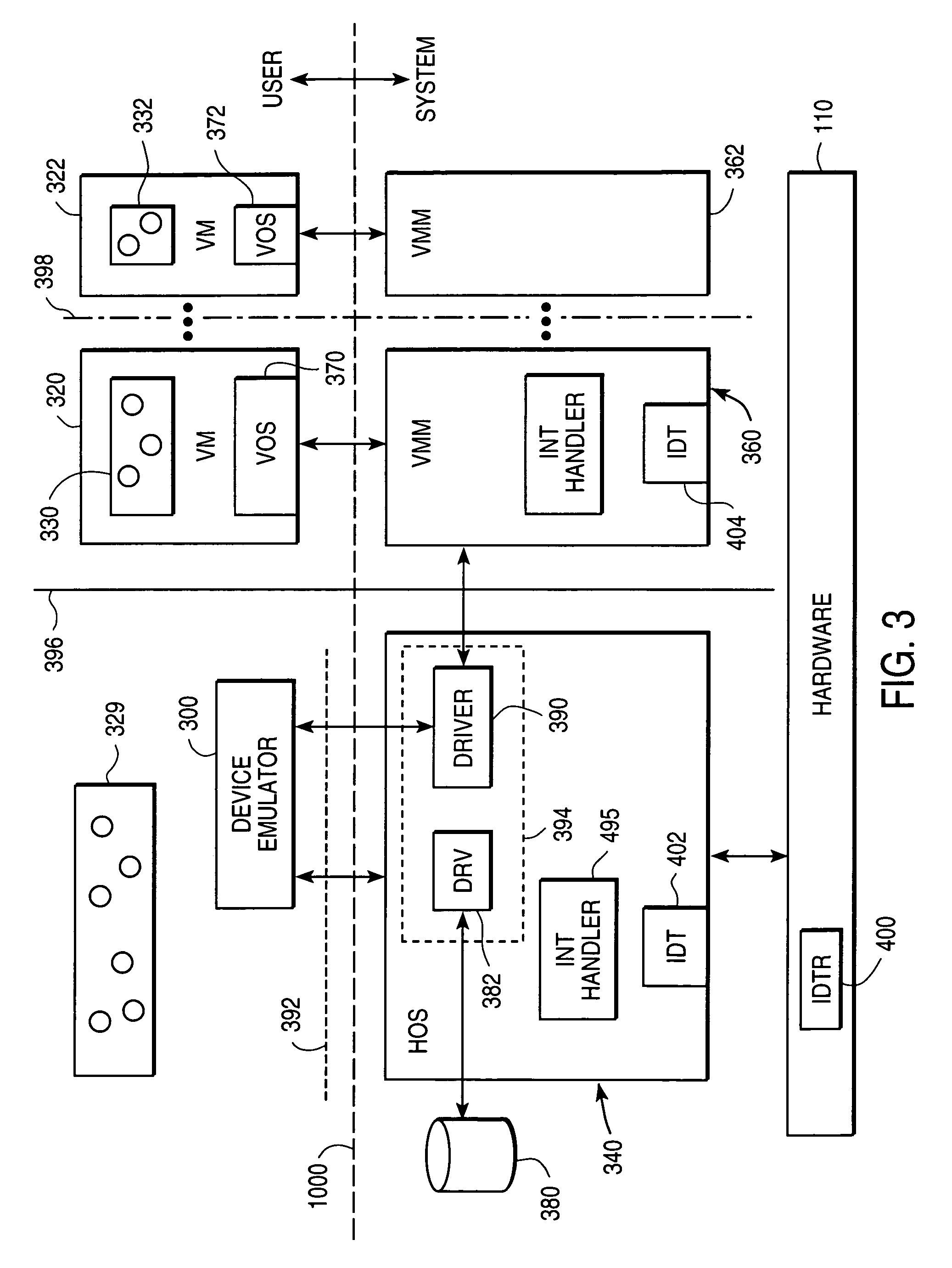
[0037]The invention virtualizes a computer that includes a host processor, memory, and physical system devices. A conventional operating system (referred to below as the “host operating system” or “HOS”) is installed on the hardware. The computer is operationally divided into a system level and a u

Problems solved by technology

All of these known systems fail to meet one or more of the following goals:1) to provide the advantages offered by traditional virtual machine monitors, such as the ability to run multiple arbitrary operating systems concurrently.

Method used


Image

  • System and method for facilitating context-switching in a multi-context computer system
  • System and method for facilitating context-switching in a multi-context computer system
  • System and method for facilitating context-switching in a multi-context computer system

Examples


Embodiment Construction

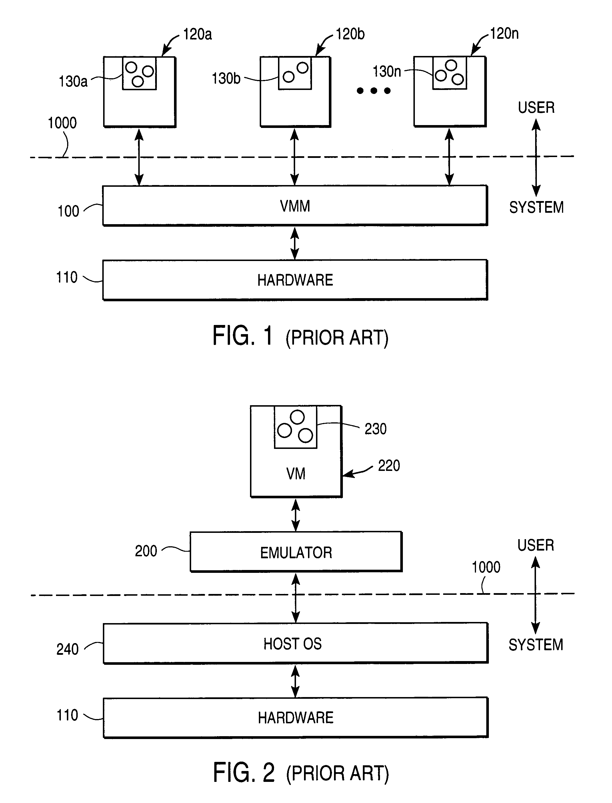
[0051]The invention is described below in sections for the sake of clarity. First, two conventional architectures are described in order to make it easier to see the unique features of the invention by way of comparison. Then, the system according to the invention is described as a whole. Finally, the main novel features of the invention are described individually.

[0052]Conventional Virtual Machine Monitor Architectures

[0053]FIG. 1 illustrates the conventional system model that incorporates a virtual machine monitor (VMM). The VMM 100 in this known architecture directly accesses the system hardware 110. This hardware includes such known structures as the system processor (one or more) itself, its registers, associated memory devices, any memory management unit MMU, I / O devices, any co-processors, and so on. One or more virtual machines 120a, 120b, . . . , 120n communicate with the VMM 100. Running on each virtual machine is a set of one or more application programs, which are symbol...


PUM


Abstract

A virtual machine monitor (VMM) is included in a computer system that has a protected host operating system (HOS). A virtual machine running at least one application via a virtual operating system is connected to the VMM. Both the HOS and the VMM have separate operating contexts and disjoint address spaces, but are both co-resident at system level. A driver that is downloadable into the HOS at system level forms a total context switch between the VMM and HOS contexts. A user-level emulator accepts commands from the VMM via the system-level driver and processes these commands as remote procedure calls. The emulator is able to issue host operating system calls and thereby access the physical system devices via the host operating system. The host operating system itself thus handles execution of certain VMM instructions, such as accessing physical devices.

Description

CROSS-REFERENCE TO RELATED APPLICATIONS[0001]This application is a continuation of and claims priority of U.S. patent application Ser. No. 09 / 151,175, filed 10 Sep. 1998, now U.S. Pat. No. 6,496,847 which in turn claims priority from U.S. Provisional Patent Application No. 60 / 085,685, filed 15 May 1998.BACKGROUND OF THE INVENTION[0002]1. Field of the Invention[0003]This invention relates to a computer architecture, including a virtual machine monitor, and a related operating method that allow virtualization of the resources of a modern computer system.[0004]2. Description of the Related Art[0005]The operating system plays a special role in today's personal computers and engineering work stations. Indeed, it is the only piece of software that is typically ordered at the same time the hardware itself is purchased. Of course, the customer can later change operating systems, upgrade to a newer version of the operating system, or even re-partition the hard drive to support multiple boots...

Claims


Application Information

Patent Timeline
IPC IPC(8): G06F9/455
CPCG06F9/45533
Inventor BUGNION, EDOUARDDEVINE, SCOTT W.ROSENBLUM, MENDEL
Owner VMWARE INC
Learn More