Method and apparatus for saving microprocessor power when sequentially accessing the microprocessor's instruction cache

a technology of instruction cache and microprocessor, applied in the direction of memory adressing/allocation/relocation, generating/distributing signals, instruments, etc., can solve the problems of high cost of air-conditioning room where many computers are stored, large space occupation, and high cost of air-conditioning room, so as to reduce power in multi-way set associative arrays.

a technology of instruction cache and microprocessor, applied in the direction of memory adressing/allocation/relocation, generating/distributing signals, instruments, etc., can solve the problems of high cost of air-conditioning room where many computers are stored, large space occupation, and high cost of air-conditioning room, so as to reduce power in multi-way set associative arrays.

US6944714B2Inactive Publication Date: 2005-09-13HEWLETT PACKARD DEV CO LP

Image

  • Method and apparatus for saving microprocessor power when sequentially accessing the microprocessor's instruction cache
  • Method and apparatus for saving microprocessor power when sequentially accessing the microprocessor's instruction cache
  • Method and apparatus for saving microprocessor power when sequentially accessing the microprocessor's instruction cache

Examples


Embodiment Construction

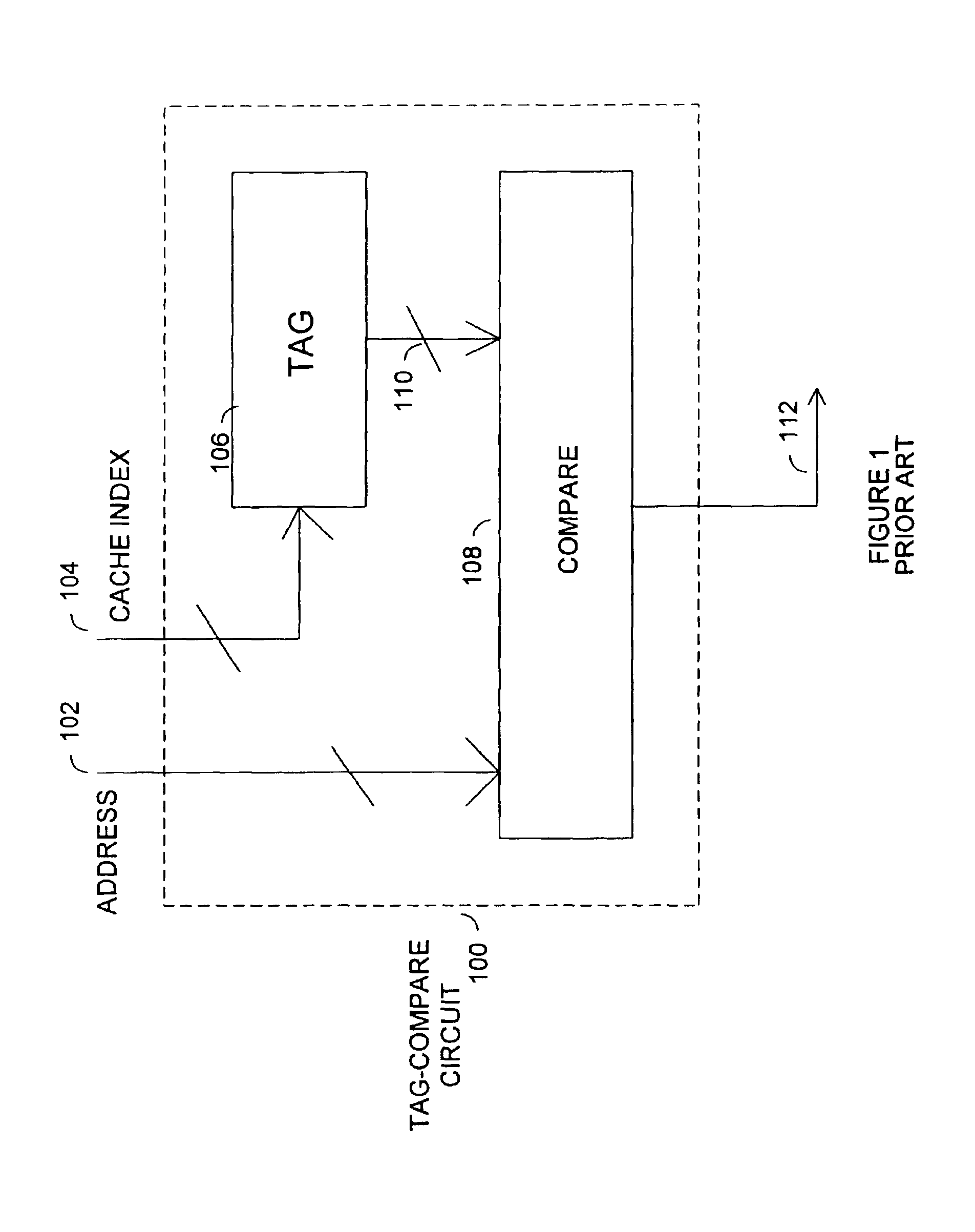
[0013]FIG. 1 is a block diagram of a tag-compare circuit, 100, containing a tag RAM (random access memory), 106, and a compare circuit, 108. A cache index, 104, is sent to the tag RAM, 106 where the cache index, 104, references an address, 110. The address from the tag RAM, 110, is then sent to the compare circuit, 108. The compare circuit, 108, compares the current address, 102, with the address, 110, taken from the tag RAM, 106. If the two addresses, 110 and 102, match, the compare-circuit, 108, sends a signal indicating a match. The tag-compare circuit, 100, is used in FIG. 2. Only the inputs and outputs of the tag-compare circuit, 100 are shown in FIG. 2 in order to make FIG. 2 easier to follow. The tag-compare circuit in FIG. 2 retains all the features described in FIG. 1.

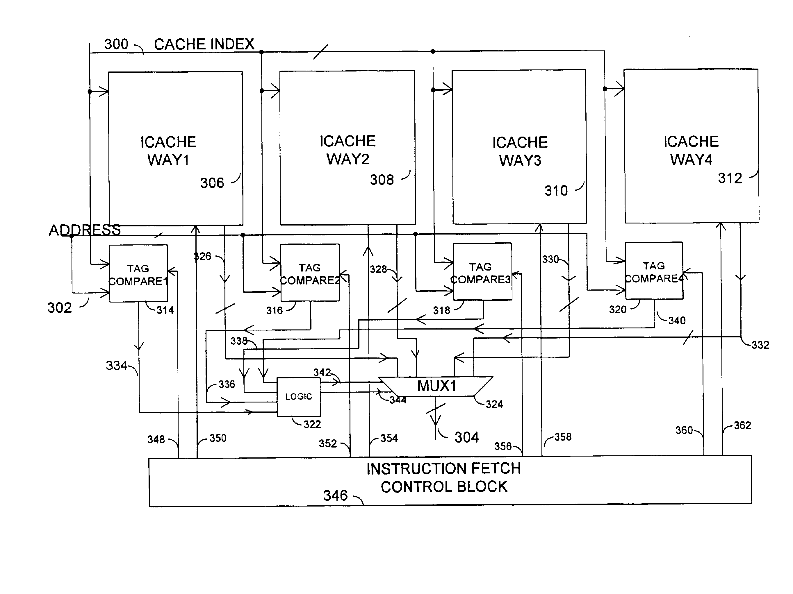
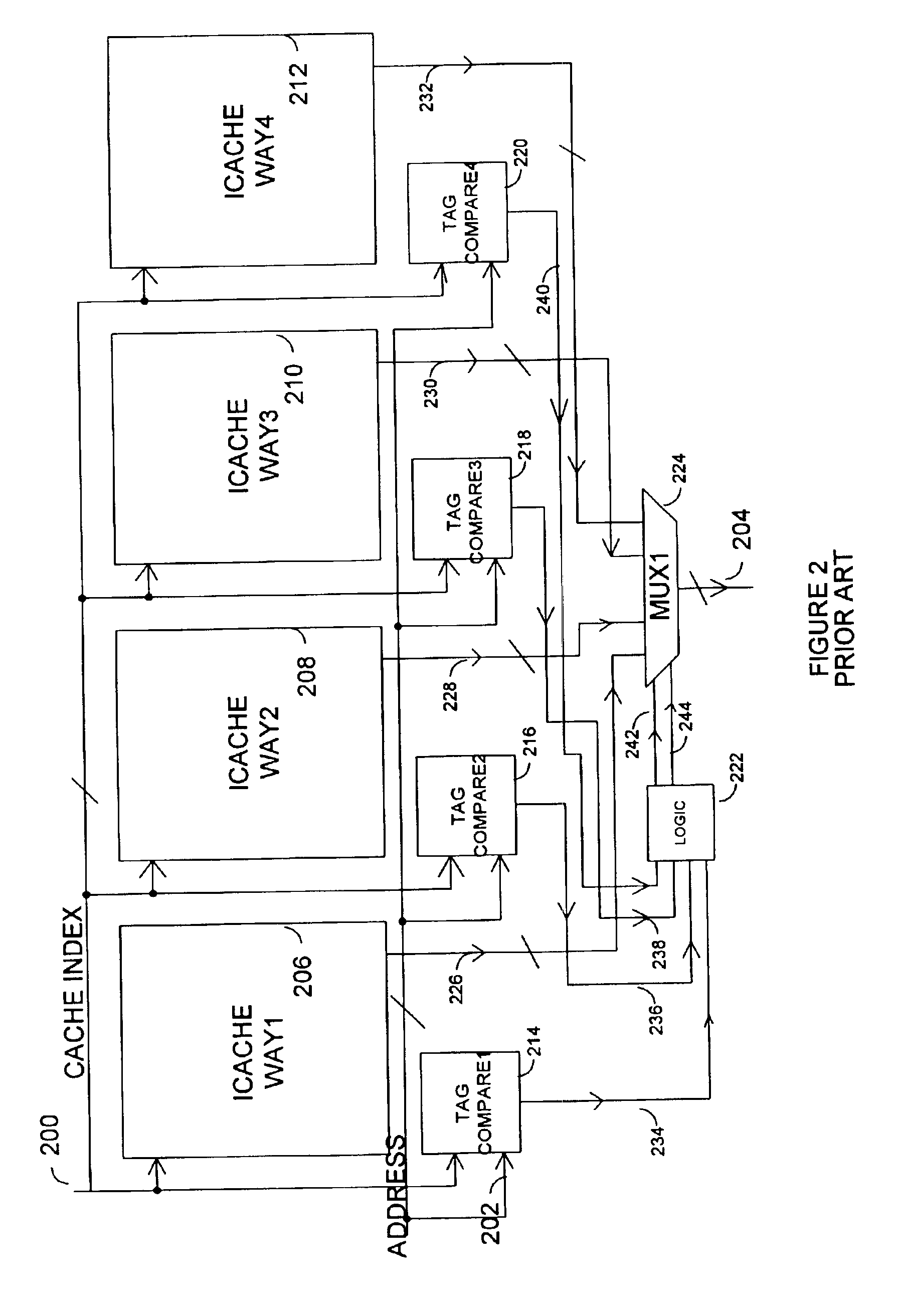
[0014]FIG. 2 shows a diagram of the functional structure of a four-way set associative instruction cache array. The four-way set associative instruction cache array contains four icache ways, 206, 208, 210, an...


PUM


Abstract

An embodiment of the invention provides a circuit and method for reducing power in multi-way set associative arrays. A control circuit detects when the next cache access will be taken from the same cache way that the previous cache access was taken from. If the next cache access is taken from the same cache way as the previous cache access, the control circuit signals all the cache ways, except the cache way that was previously accessed, to not access information from their arrays. The control circuit also signals the tag arrays to not access their information and disables power to all the compare circuits. In this manner, power may be reduced when sequentially accessing information from one cache way in a multi-way set associative array.

Description

FIELD OF THE INVENTION[0001]This invention relates generally to microprocessor power. More particularly, this invention relates to reducing power in a microprocessor when sequentially accessing the microprocessor's instruction cache.BACKGROUND OF THE INVENTION[0002]As more electronic circuits are included on a single die, the power dissipated by a single die continues to increase. In order to keep the temperature of a single IC (integrated circuit) at a reasonable temperature, many techniques have been used. For example, elaborate cooling fins have been attached to the substrate of ICs. Also, fans have been positioned near a group of IC's to cool them. In some cases, liquids have been used to transfer the heat produced by ICs. These solutions can be costly and may require a great deal of space, where space is at a premium.[0003]In addition, the cost to air condition rooms where many computers are stored can be costly. Another problem created by ICs consuming more and more power is t...

Claims


Application Information

Patent Timeline
13 Sep 2005
Publication
US6944714B2
IPC
G06F1/32; G06F12/08
CPC
G06F1/3225; G06F1/3275; G06F12/0864; G06F12/0882; Y02B60/1228; G06F2212/1028; Y02B60/1225; G06F9/3802
Inventors
LESARTE, GREGG B.; BOCKHAUS, JOHN W.