Fixed-line trimmer head

a trimmer and fixed-line technology, applied in metal working apparatus, agriculture tools and machines, agriculture, etc., can solve the problems of not always taking place, the line which is wound on the storage reel in the hub tends to get stuck, and the line feeding from the hub is not always easy to carry, so as to facilitate the insertion of a length of line, easy to load with the trimmer, and simple and rapid removal of line

Inactive Publication Date: 2005-09-20
ROTARY CORP
View PDF13 Cites 62 Cited by
  • Summary
  • Abstract
  • Description
  • Claims
  • Application Information

AI Technical Summary

Benefits of technology

[0017]It is a further object of this invention to provide a fixed line trimmer head for string trimmer machines which is easy to load with trimmer line of various diameters, and which employs spring retaining tabs at each o

Problems solved by technology

A problem exists with bump and feed trimmers, however, in that frequently the line which is wound on the storage reel in the hub tends to become stuck, either due to partial fusion of the line within the hub, caused by high frequency vibration, or by successive turns of the line wound on the hub becoming somewhat entangled.
As a result, feeding of the line from the hub, when desired, does not always take place.
This is a very time consuming and frustrating experience for many users of flexible line string trimmers.
Due to the hole design and pattern, smaller standard sized lines (under about 0.095″ diameter) have a tendency to slip out of commercial fixed heads during operation.
Because the guide surfaces are close together and 0.130″ diameter line is relatively stiff, it is difficult to install and remove sections of nylon line from the Echo® trimmer head.
This difficulty results in excessive time being consumed for the removal and replacement of line segments.
A problem which exists with this type of trimmer head and line combination, however, is that each le

Method used


Image

  • Fixed-line trimmer head
  • Fixed-line trimmer head
  • Fixed-line trimmer head

Examples


Embodiment Construction

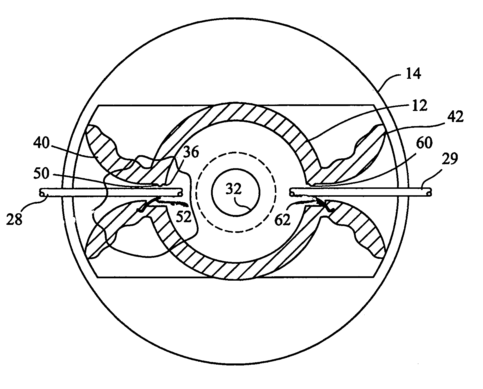
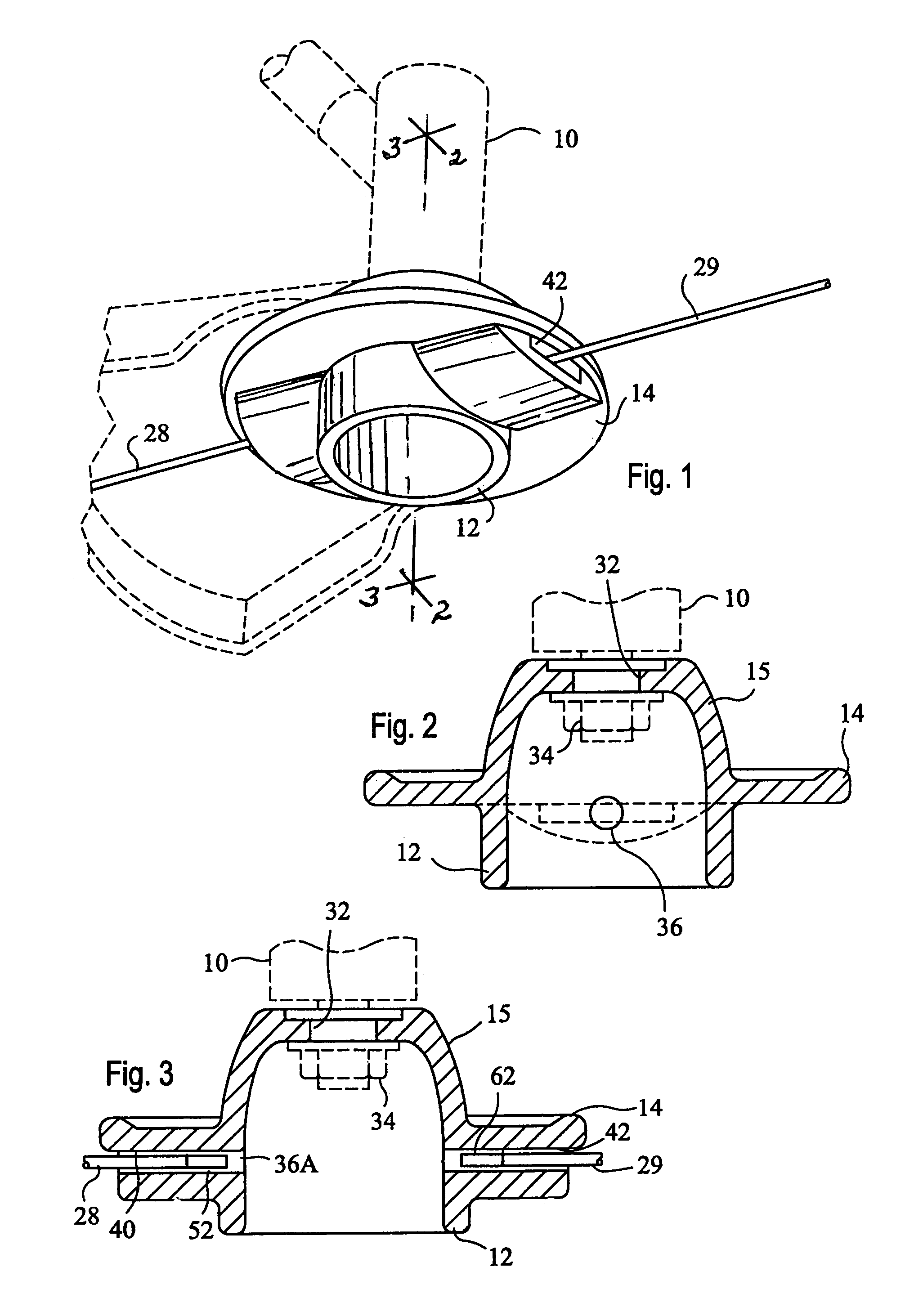
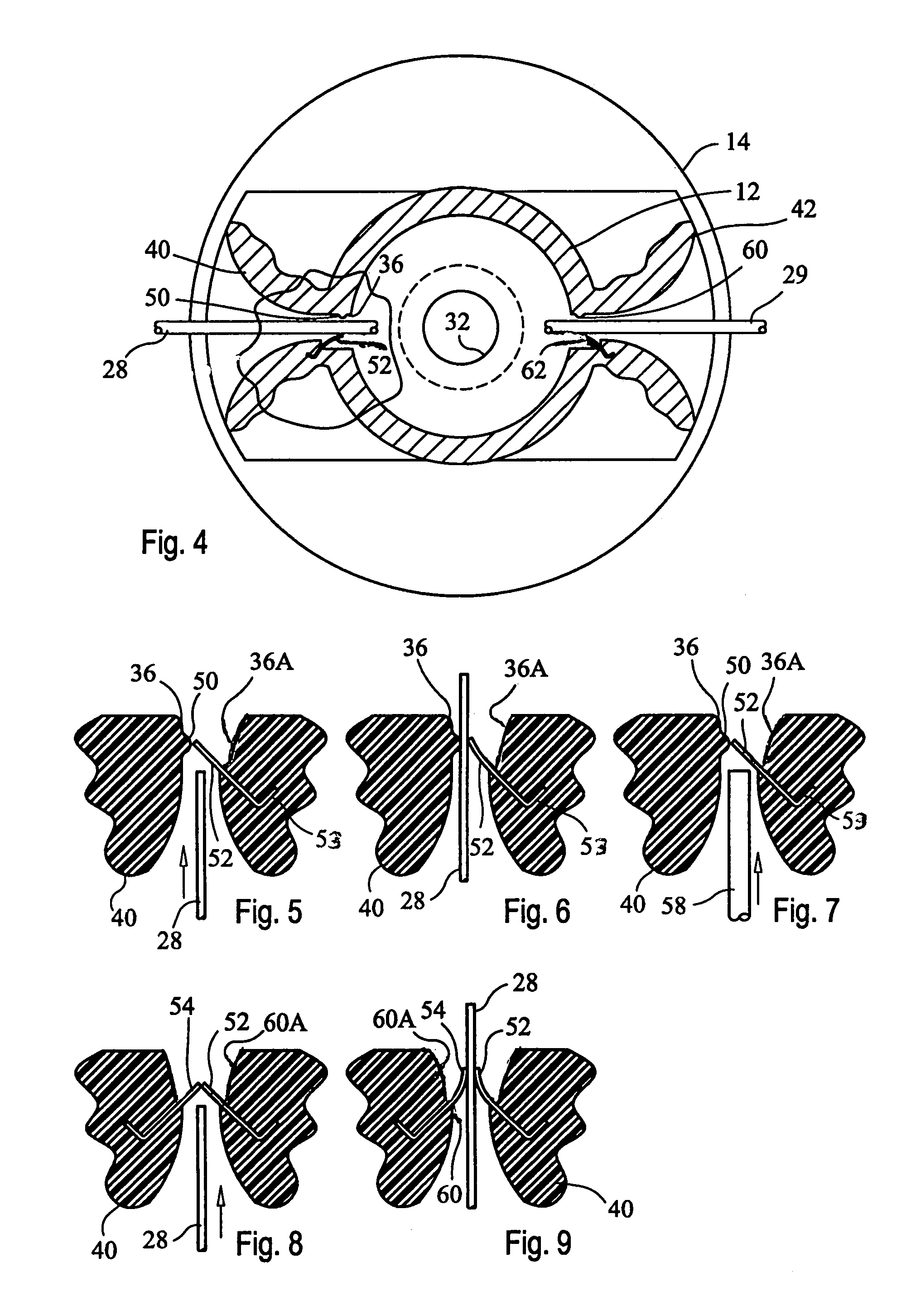
[0029]Reference now should be made to the drawings, in which the same reference numbers are used throughout the different figures to designate the same components. FIG. 1 is a bottom perspective view of a fixed line head for a string trimmer machine with which a preferred embodiment of the invention may be used.

[0030]The trimmer head is designed to be attached in place on the end of the operating shaft of a string trimmer machine 10. The head comprises a central cylindrically shaped main housing 12, with a circular flange 14 located intermediate its length. The lower end of the housing 12 is open, as is readily apparent from an examination of FIGS. 1,2 and 3. The upper end of the housing comprises a portion 15 located above the flange 14. The end of the portion 15 is substantially closed, with a hole 32 formed through it. As shown in FIG. 2, the hole 32 is used to accommodate the drive shaft of the string trimmer machine 10, which then is secured to the housing 12 / 14 / 15 by means of ...


PUM


Abstract

A trimmer head for string trimmer machines uses a fixed line segment inserted into a passageway in the trimmer head housing where the line is engaged by a trimmer line retaining tab secured in the main housing and extending into the passageway for engagement by a trimmer line segment inserted into an entry opening.

Description

BACKGROUND[0001]Weed and grass trimmers have been developed which employ a rotatable hub with a short length of flexible nylon or other plastic line extending from the hub. When the hub is rotated (typically at speeds from 6,000 RPM to 12,000 RPM), the tip of the line extending from the hub provides the cutting or trimming action. Grass and weed trimmers using this principle of operation have become popular for their versatility of use and because the flexible trim line is safer to use than rigid rotating steel blades.[0002]Various types of devices have been developed for using such trim lines. Typically, rotating line trimmers or rotating string trimmers employ a line which generally has a circular cross section. The line, in many trimmers, is wound on a storage reel in the hub of the device and is fed out of a hole in the hub in discrete amounts, as the end breaks off or wears off. Trimmers of this type sometimes are referred to as “bump and feed” trimmers, since, when the line br...

Claims


Application Information

Patent Timeline
IPC IPC(8): A01D34/00A01D34/84A01D34/416
CPCA01D34/4166
Inventor FOGLE, JOHN R.
Owner ROTARY CORP
Why Eureka
Try Eureka