Free piston engine and power generation system therewith

a free piston engine and power generation system technology, which is applied to machines/engines, engines without rotary main shafts, and positive displacement liquid engines, etc., can solve the problems of difficulty in controlling the free piston engine, the inability to easily reduce the periodic vibration due to the explosion, and the inability to effectively extract the energy generated by the explosion of gases within the combustion chamber. , to achieve the effect of reducing the loss of energy, increasing efficiency, and reducing vibration

Inactive Publication Date: 2005-09-20
DENSO CORP
View PDF6 Cites 46 Cited by
  • Summary
  • Abstract
  • Description
  • Claims
  • Application Information

AI Technical Summary

Benefits of technology

[0011]It is an object of the present invention to provide a highly durable free piston engine where the vibration is decreased without the size enlarged. Further, it is another object of the present invention to provide a power generation system where output can be increased without the size enlarged.
[0013]In this structure, the first spring unit and the second spring unit accumulate as elastic potential energy a part of the energy that the first piston and the second piston obtain because of the explosion in the combustion chamber. The first spring unit and the second spring unit then regenerate the accumulated elastic potential energy into kinetic energy to thereby push back the first piston and the second piston towards the combustion chamber. The loss in the energy can be thereby decreased, which increases the efficiency. Further, the first piston and the second piston are disposed oppositely to each other, so that vibrations due to the movements of the first piston and the second piston are offset by each other. This prevents necessity of increase in the number of the cylinders for decreasing the vibrations. Further, the first piston and the second piston are supported by the first spring unit and the second spring unit, respectively. This decreases contact of the first piston and the second piston with the housing forming the cylinder, and friction due to this contact. Therefore, without the free piston engine becoming large-sized, the vibration can be decreased and the durability can be enhanced.

Problems solved by technology

However, in a two-cylinder free piston engine constituted by the two combustion chambers, periodic vibrations due to the explosions cannot be easily decreased.
As a result, the energy generated from the explosion of the gases within the combustion chamber cannot be effectively extracted.
This eventually entails difficulty in control of the free piston engine, complication in structure, and a large size.
The contact surfaces of the pistons and cylinders easily undergo friction, resulting in decrease in durability.
Further, the circumferential rotations of the pistons are not easily controlled.
The surface area where the magnetic field varies becomes small, which results in decrease in efficiency.
This entails increase in weight and size in the free piston engine.

Method used


Image

  • Free piston engine and power generation system therewith
  • Free piston engine and power generation system therewith
  • Free piston engine and power generation system therewith

Examples


first embodiment

[0025](First Embodiment)

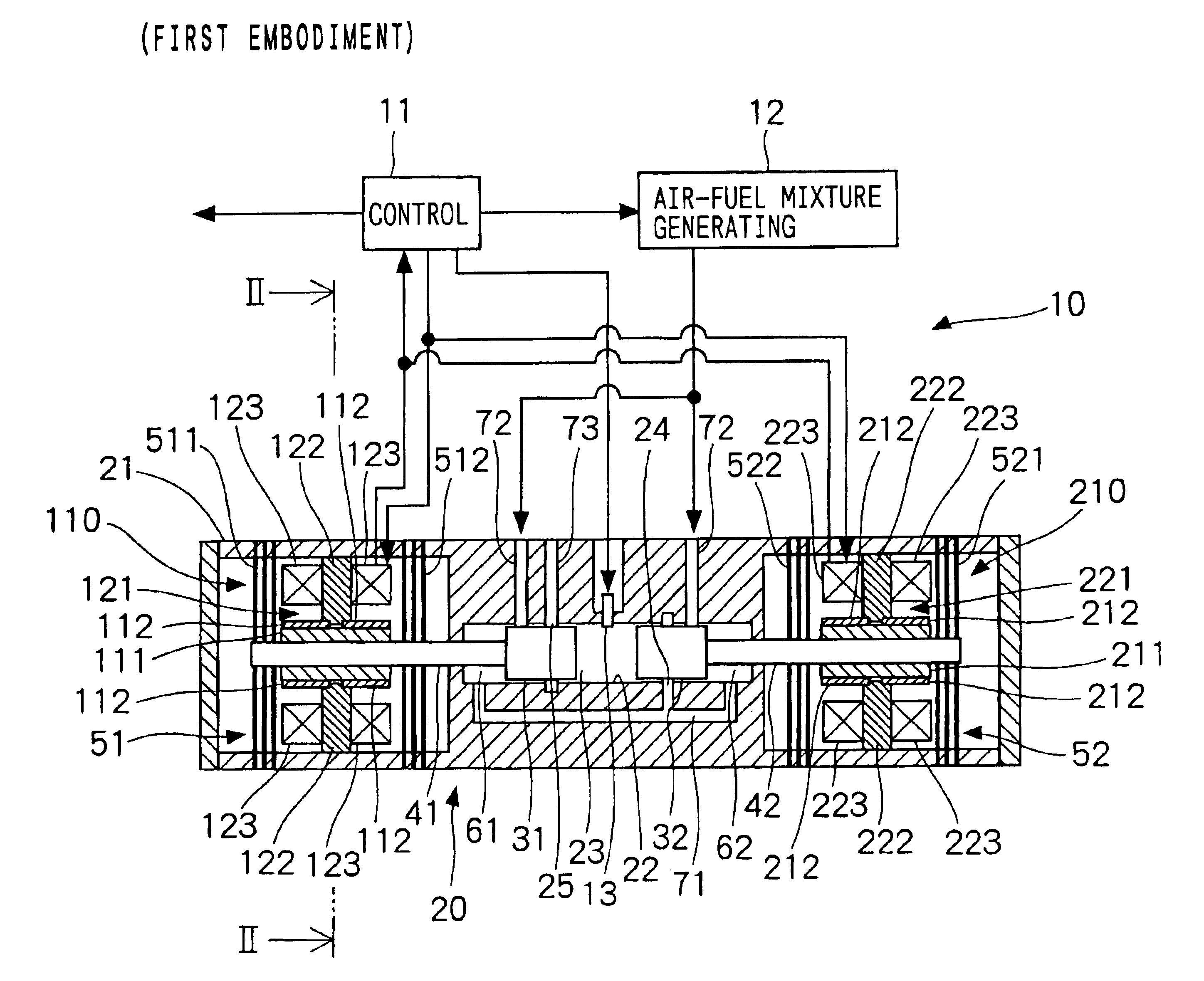
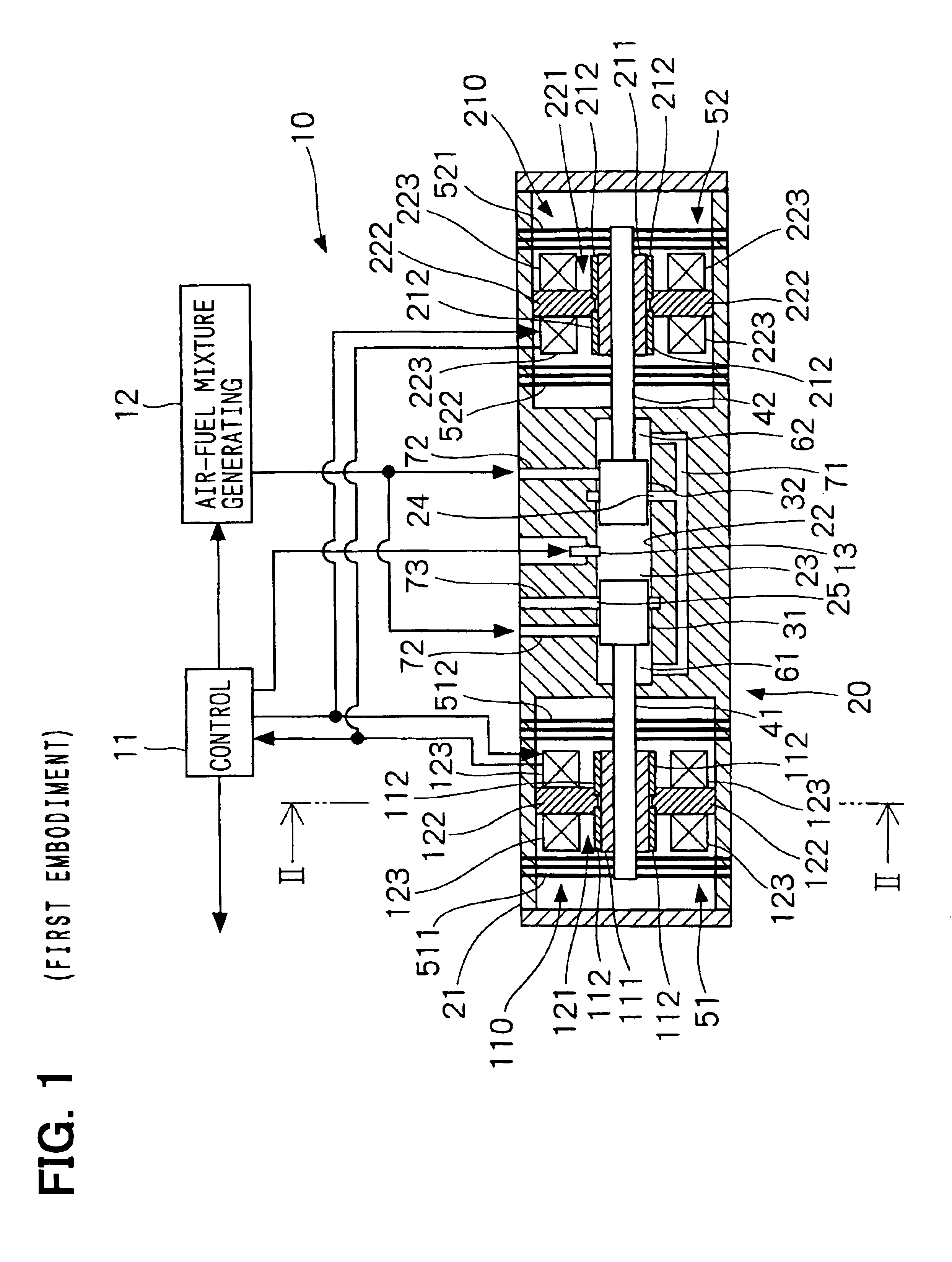
[0026]A free piston engine according to a first embodiment of the present invention is directed to a power generation system, of which a schematic cross sectional view is shown in FIG. 1. The power generation system 10 includes a linear motor generator as a loading unit that applies a load to the free piston engine. For instance, the power generation system 10 is connected with a motor via an external battery (not shown). For instance, the power generation system 10 is used as a motive energy source for a small-sized vehicle or a motive energy source for a series-type hybrid vehicle.

[0027]The power generation system 10 includes a free piston engine 20 that is integrated into the power generation system 10; a first linear motor generator 110; and a second linear motor generator 210. The power generation system 10 further includes a control unit 11, an air-fuel mixture generating unit 12, and an ignition plug 13 as an ignition unit. The control unit 11 executes...

second embodiment

[0056](Second Embodiment)

[0057]A power generation system 80 according to a second embodiment will be explained with reference to FIG. 5. Structural elements substantially equal to those in the first embodiment have the same reference numbers, so that the explanation for the equal elements will be removed below.

[0058]The free piston engine 20 in the power generation system 80 is provided with an intake valve 81 and an exhaust valve 82 as a valve unit. The power generation system 80 includes an intake valve actuator 83 and an exhaust valve actuator 84, both of which include, e.g., an electromagnetic actuator or a piezoelectric actuator. The intake valve 81 is disposed in a scavenging passage 85, and opens and shuts the connection between the scavenging passage 85 and the combustion chamber 23. The exhaust valve 82 is disposed in an exhaust passage 86, and opens and shuts the connection between the exhaust passage 86 and the combustion chamber 23. The intake valve actuator 83 and the e...

third embodiment

[0061](Third Embodiment)

[0062]A power generation system 100 according to a third embodiment will be explained with reference to FIGS. 6 to 10. Structural elements substantially equal to those in the first embodiment have the same reference numbers, so that the explanation for the equal elements will be removed below.

[0063]A free piston engine 120 in the power generation system 100 is provided with an intake valve 101 and an exhaust valve 102 as a valve unit. The power generation system 100 includes an intake valve actuator 103 for opening and closing the intake valve 101 and an exhaust valve actuator 104 for opening and closing the exhaust valve 102. The intake valve 81 is disposed in an intake passage 105, and connects and closes the intake passage 105 to the combustion chamber 23. The exhaust valve 102 is disposed in an exhaust passage 106, and connects and closes the exhaust passage 106 to the combustion chamber 23. The intake valve actuator 103 and the exhaust valve actuator 104...


PUM


Abstract

A first piston connected to a first shaft and a second piston connected to a second shaft are supported within a housing by using a first leaf-spring unit and a second leaf-spring unit, respectively. Therefore, axial movement of the first shaft or the second shaft can be allowed, while circumferential rotational movement and radial movement can be restricted. The first leaf-spring unit includes two leaf-spring groups that are disposed in a row around the first shaft in the direction of the axis of the first shaft; similarly, the second leaf-spring unit includes two leaf-spring groups that are disposed in a row around the second shaft in the direction of the axis of the second shaft. Therefore, inclinations of the first shaft and the second shaft can be decreased. This results in reduction in contact between the first and second shafts and a cylinder within the housing and friction due to the contact.

Description

CROSS REFERENCE TO RELATED APPLICATIONS[0001]This application is based on and incorporates herein by reference Japanese Patent Application No. 2003-391226 filed on Nov. 20, 2003.FIELD OF THE INVENTION[0002]The present invention relates to a free piston engine and a power generation system therewith.BACKGROUND OF THE INVENTION[0003]Conventionally, a free piston engine is known as an engine that needs no crank, no connecting rod, and no piston pin bearing and that can be compact. Further, in Patent document 1, a power generation system uses a free piston engine as its power source. Here, the free piston engine has a magnet portion disposed in a center of an axial direction, and a shaft that has pistons at both ends. The pistons in the both ends are contained within both cylinders, respectively. The both cylinders alternately undergo explosions of gases including gasoline, so that the magnet portion is axially reciprocated.[0004]A different type of a free piston engine is also known in...

Claims


Application Information

Patent Timeline
Patent Type & Authority Patents(United States)
IPC IPC(8): F02B63/04F02B71/00F02B71/04F02B63/00F01B11/04F01B7/04F01B23/10H02K7/18H02K35/02
CPCF02B63/04F02B71/04H02K7/1884F02B63/041
Inventor KANEKO, TAKASHIHAGIWARA, YASUMASAMII, WATARUOJIKA, KAZUHIRO
Owner DENSO CORP
Why Eureka
Try Eureka