
Measuring apparatus for measuring the cloth tension in a weaving machine and a weaving machine with a measuring apparatus of this kind

a technology of measuring apparatus and weaving machine, which is applied in the direction of looms, shuttles, textiles and paper, etc., can solve the problems of double-beam weaving machines, special problems, and inability to adapt the measurement position transversely to the direction of cloth travel, etc., and achieve the effect of simple and precis

Inactive Publication Date: 2005-09-20
SULZER TEXTIL AG
View PDF9 Cites 0 Cited by
  • Summary
  • Abstract
  • Description
  • Claims
  • Application Information

AI Technical Summary

Benefits of technology

[0004]An object of the invention is to provide a simple and precise measuring apparatus for the measurement of the cloth tension in a weaving machine which avoids the disadvantages of the prior art, and which is also suitable in particular for the measurement of the cloth tension in double beam weaving machines. A further object of the invention is to provide a weaving machine with at least one measuring apparatus of this kind.
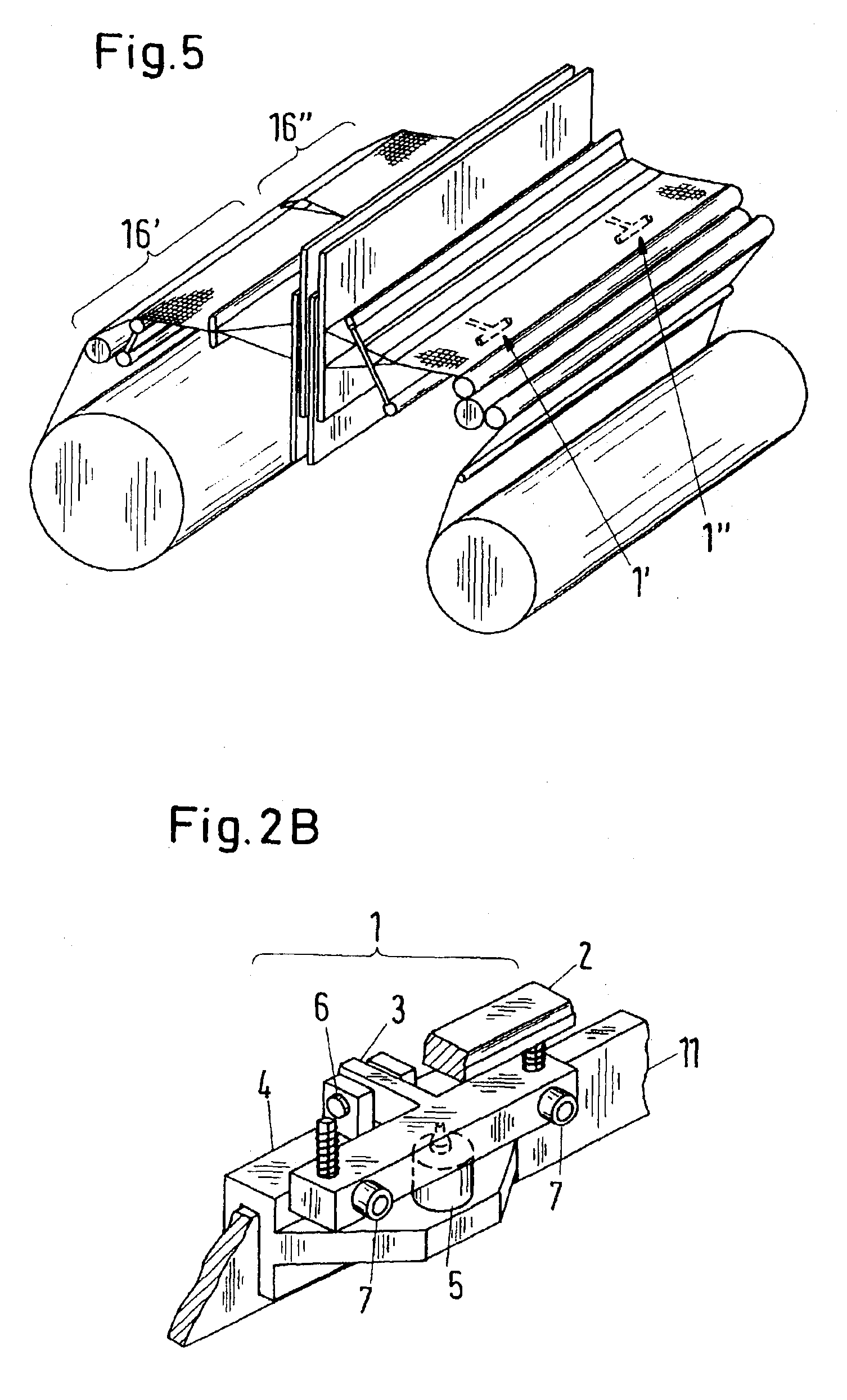
[0008]The measuring apparatus in accordance with the invention has the advantage that the measurement position can largely be freely chosen, since the measuring apparatus is executed as a module. The measuring apparatus in accordance with the invention can for example be arranged displaceably on a carrier section, through which a displaceability transverse to the direction of travel of the cloth can be achieved in a simple manner. As was initially mentioned, in double beam weaving machines it is particularly important for the measuring apparatus for the measurement of the cloth tension to be laterally displaceable when the cloth width is changed. In contrast to this, numerous measuring apparatuses for the measurement of the cloth tension are known from the prior art which are either integrated into the drive parts or cloth guiding parts of the weaving machine or use such parts as an integral component. In these solutions the measurement position is predetermined by the weaving machine parts used and can be changed only with a greater amount of effort.
[0009]A further advantageous property of the solution in accordance with the invention consists in that the probe element and the guide part can be manufactured with comparatively low mass, since they are independent of the drive parts and cloth guiding parts of the weaving machine. The measuring apparatus in accordance with the invention is thus suitable for high dynamic response, and the mass of the probe element and the guide part can be chosen such that the influence of oscillations of the weaving machine remains small.

Problems solved by technology

This is considered disadvantageous since these solutions are not very flexible.
A simple adaptation of the measurement position transversely to the direction of travel of the cloth is however not possible with the mentioned measuring apparatuses from the prior art.
In this regard, double beam weaving machines present a special problem.

Method used


Image

  • Measuring apparatus for measuring the cloth tension in a weaving machine and a weaving machine with a measuring apparatus of this kind
  • Measuring apparatus for measuring the cloth tension in a weaving machine and a weaving machine with a measuring apparatus of this kind
  • Measuring apparatus for measuring the cloth tension in a weaving machine and a weaving machine with a measuring apparatus of this kind

Examples


Embodiment Construction

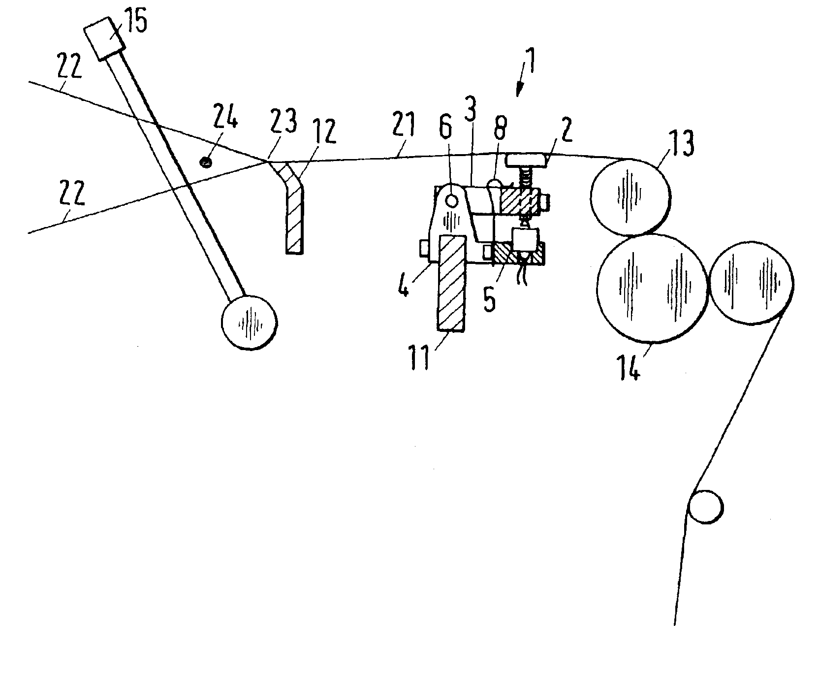
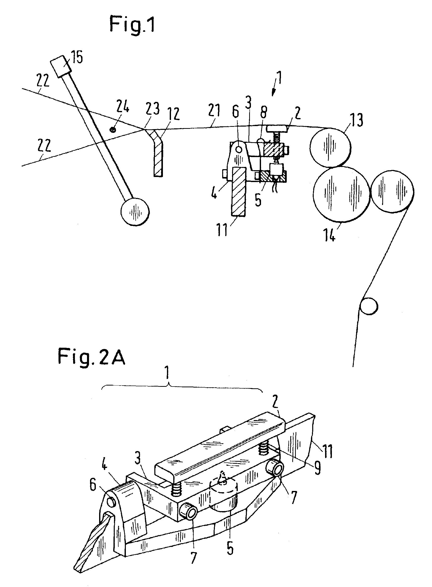
[0018]FIG. 1 shows a side view of a first embodiment of a measuring apparatus for the measurement of the cloth tension in accordance with the present invention. The side view of FIG. 1 shows the measuring apparatus in the installed state. In this the cloth 21, which is formed at the beat-up line 23, i.e. at the cloth edge, is guided over a cloth support 12 and further over a probe element 2 of the measuring apparatus 1 to a deflection roller 13 and then to a cloth drive 14. A fixed breast beam section can also be provided in place of the deflection roller 13, the so-called breast beam, at the same position. The probe element 2 of the measuring apparatus 1 is arranged in such a manner that the cloth 21 is pressed upwards slightly by the probe element 2 in order to pick up a contact pressure which is produced by the cloth tension and a force vector resulting therefrom. FIG. 1 also illustrates a reed 15, weft yarns 22, and an inserted weft thread 24.

[0019]In the embodiment the probe el...


PUM


Abstract

A measuring apparatus for the measurement of the cloth tension in weaving machines comprises a probe element and a guide part to which the probe element is connected in order to guide the probe element. The measuring apparatus furthermore comprises a holder to which the guide part is secured and a sensor element which is in contact with the probe element in such a manner that a force which acts on the probe element causes a corresponding change in the sensor element. In this the guide part is attached at one side to the holder, the probe element is spaced from the attachment of the guide part, and the measuring apparatus is executed as a module.

Description

BACKGROUND OF THE INVENTION[0001]The invention relates to a measuring apparatus for measuring the cloth tension in a weaving machine and to a weaving machine with at least one measuring apparatus of this kind. Furthermore, the invention relates to a weaving machine with two warp beams, which is equipped with at least one measuring apparatus each for the measurement of the cloth tension for each warp beam.[0002]In weaving machines the warp let-off must be regulated in such a manner that the warp tension is held constant independently of the diameter of the warp beam. For this purpose the warp tension was previously measured directly. The warp tension can however also be determined indirectly from measurements of the cloth tension. The specifications DE 39 05 881 C2 and EP 0 385 061 B2 describe “warp tension measurement devices” in which the cloth tension is measured by means of a measuring apparatus which is inserted into the breast beam. The Japanese laying-open print JP 2-293444 di...

Claims


Application Information

Patent Timeline
Patent Type & Authority Patents(United States)
IPC IPC(8): D03D49/18D03D49/04
CPCD03D49/18
Inventor MARKWARD, DIETMARGASSER, ERICH
Owner SULZER TEXTIL AG
Learn More