Al technical title is built by PatSnap Al team. It summarizes the technical point description of the patent document.
a transfer set and resealable technology, applied in the field of universal resealable transfer sets, can solve the problems of multiple uses of the transfer set, limited use of the medical valve disclosed in these patents, and inability to readily adapt to the transfer s
Inactive Publication Date: 2005-09-20
BECTON DICKINSON & CO
View PDF207 Cites 92 Cited by
Summary
Abstract
Description
Claims
Application Information
AI Technical Summary
This helps you quickly interpret patents by identifying the three key elements:
Problems solved by technology
Method used
Benefits of technology
[0010]Upon removal of the tubular portion of the syringe or second container from the longitudinal slit in the generally closed distal end portion of the fluid transfer valve member, the slit closes effectively resealing the transfer set for later use. All that is required for later reuse is to swab the surface of the exposed closed distal end with a suitable sterilizing fluid. Thus, the resealable transfer set of this invention is suitable for multiple uses, permitting storage of a greater quantity of medicament in the vial.
[0014]The transfer set assembly of this invention is resealable and suitable for multiple uses as described above and the design is relatively simple and may be manufactured at relatively low cost. The transfer set assembly is also reliable and simple to use for transferring fluids between a vial and a syringe by healthcare workers. Other advantages and meritorious features of the present invention will be more fully understood from the following description of the preferred embodiments, the appended claims and the drawings, a brief description of which follows.
Problems solved by technology
The proposed transfer sets, however, do not permit multiple uses of the transfer set, limiting their use to one application.
As set forth above, however, the prior proposed vial transfer sets are not resealable and are therefore limited to a single use.
U.S. Pat. Nos. 5,474,544, 5,549,651 and 5,697,915 disclose luer receiving medical valves having a slit silicone membrane and which eliminates the requirement for a needle cannula on the syringe, sometimes referred to as a “luer slip connector.” The medical valve disclosed in these patents are not, however, readily adaptable to a transfer set because the longitudinally slit cylindrical polymeric membrane must first be moved within the valve to a larger diameter chamber and then compressed by the luer slip connector of the syringe to expand and open the slit for transfer of fluid.
Further, the luer receiving medical valve disclosed in these patents do not provide for piercing of a closure, such as the pierceable stopper of a conventional vial.
Method used
Image
Click on the blue label to locate the original text in one second.
Reading with bidirectional positioning of images and text.
Examples
Embodiment Construction
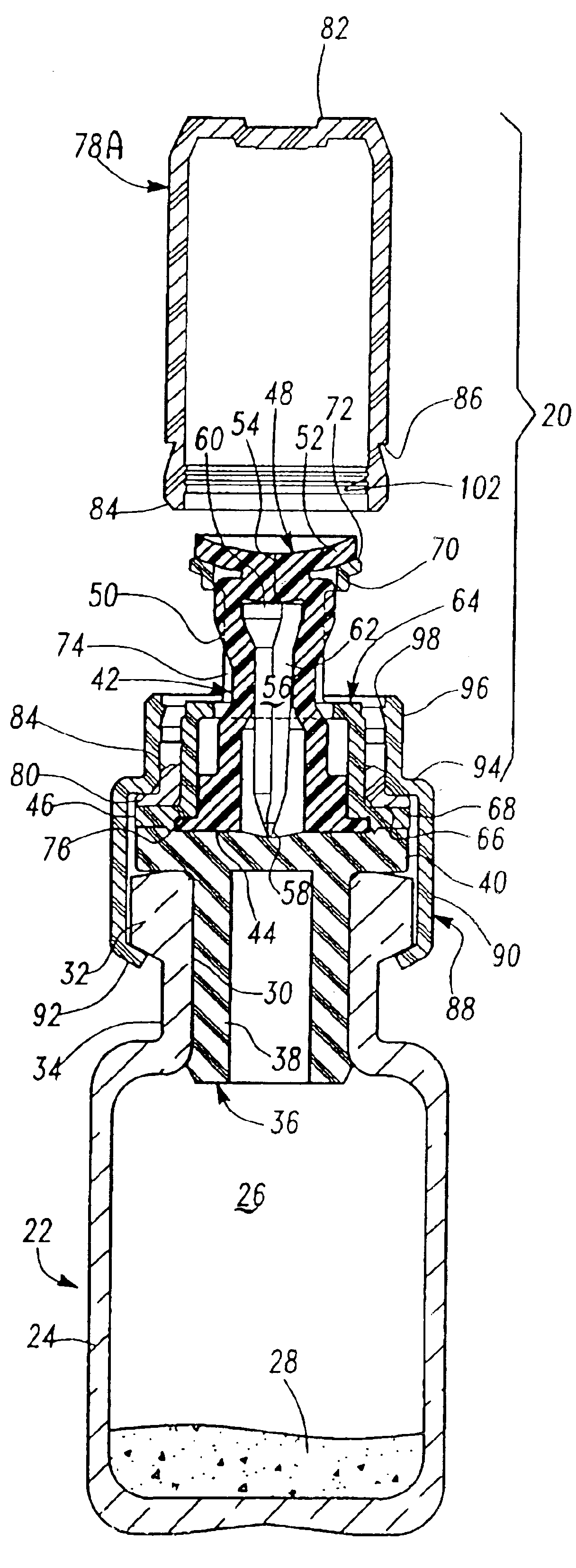
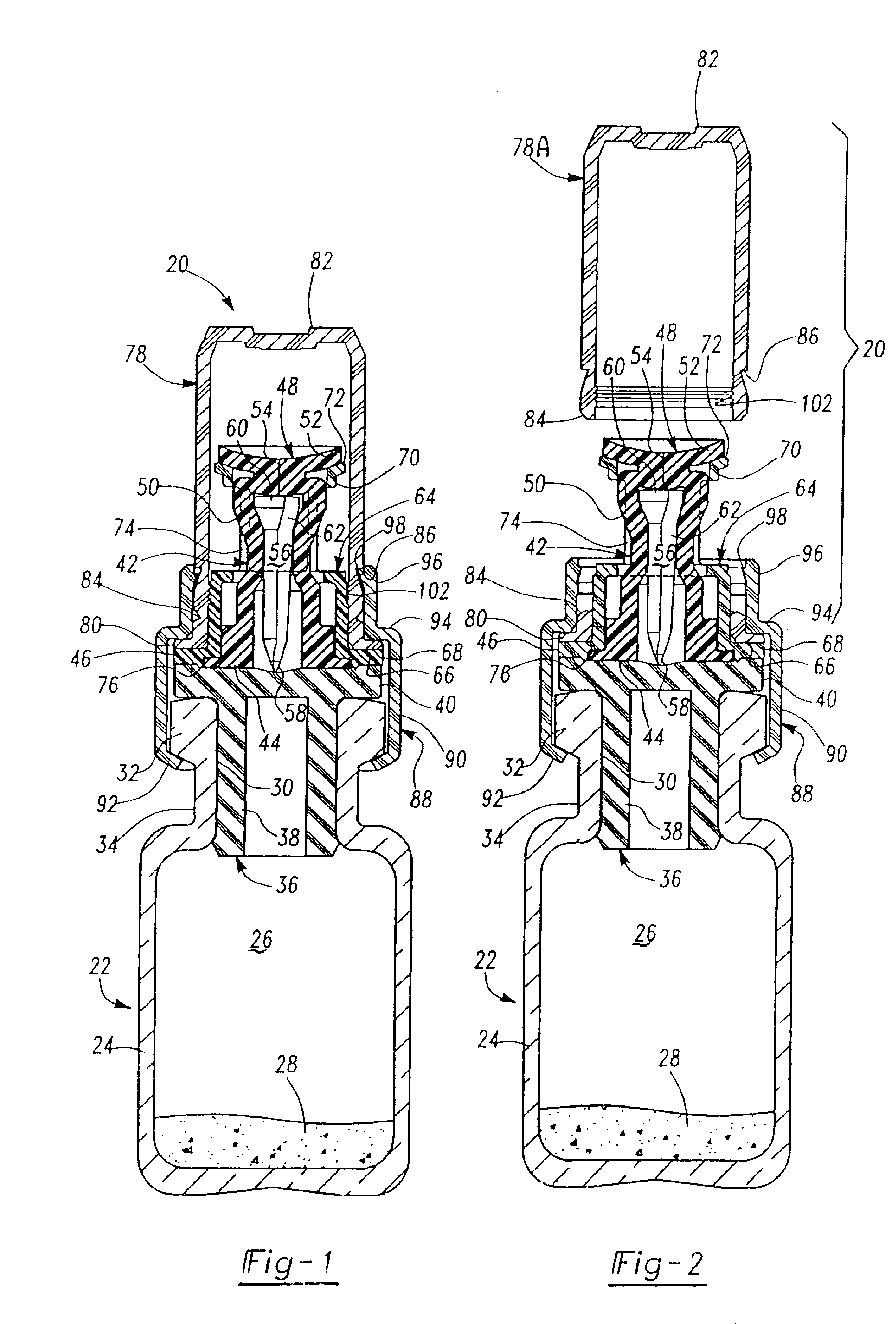
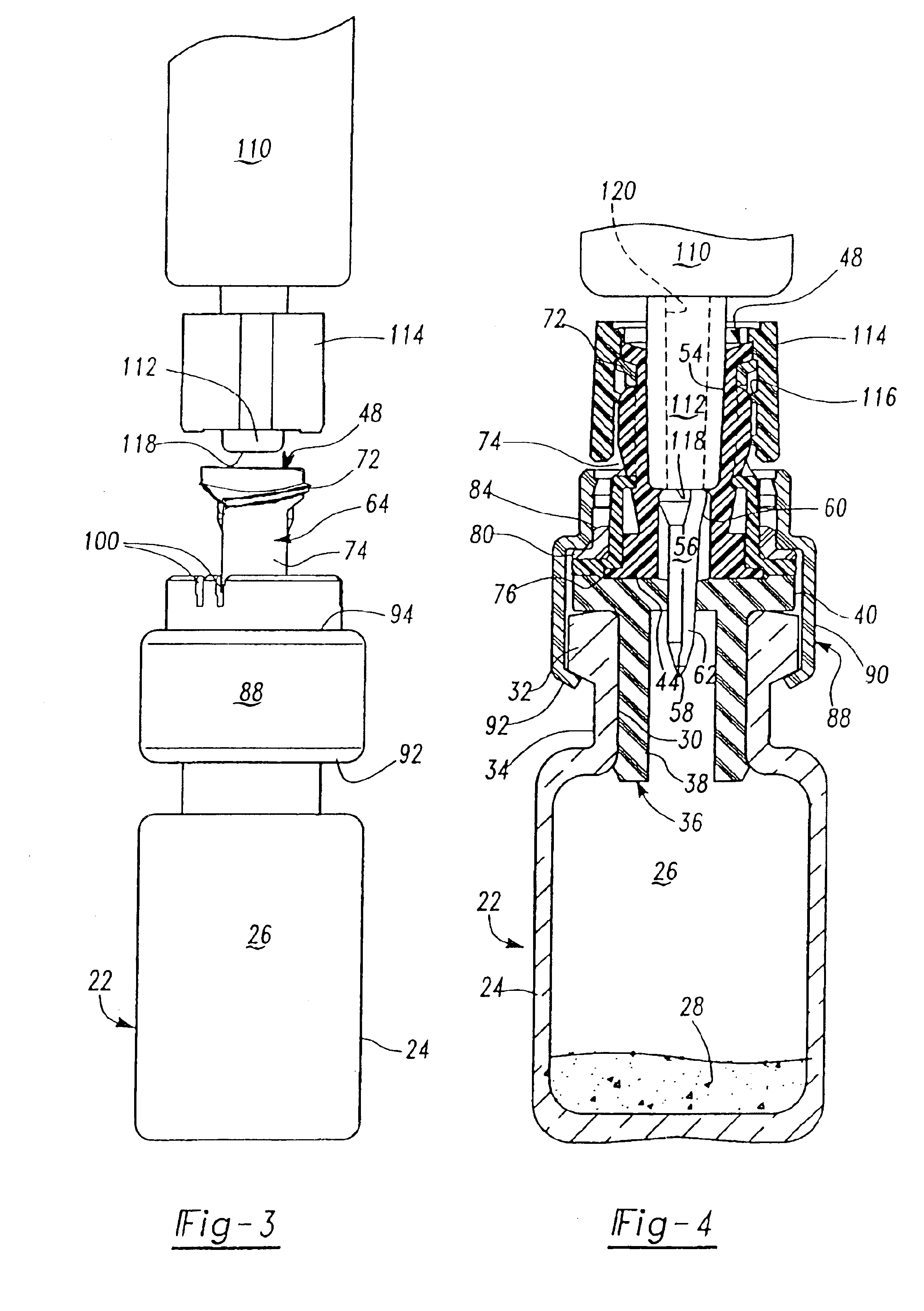
[0020]As described above, the preferred embodiments of the resealable transfer set assembly 20 of this invention may be utilized with a conventional vial 22, typically formed of glass, but may also be formed of plastic. A typical medicament vial 22 includes a body portion 24 defining an enclosure 26 which may receive dry or powdered medicament or drug for later reconstitution in liquid form by adding a diluent or solvent. The vial further includes an open end 30, a rim portion 32 surrounding the open end of the vial and a reduced diameter neck portion 34 adjacent the rim portion. Medicament vials are typically sealed with an elastomeric stopper 36 which may be formed of natural or synthetic rubber. A typical elastomeric stopper includes a tubular portion 38 having a diameter slightly greater than the internal diameter of the opening 30 to provide a good seal, and a planar rim portion 40 which overlies the rim portion 32 of the vial. As described above, however, the transfer set 20 o...
PUM
Property
Measurement
Unit
elongation at break
aaaaa
aaaaa
elongation at break
aaaaa
aaaaa
elongation at break
aaaaa
aaaaa
Abstract
A transfer set for transferring fluid, including drugs, vaccines, medicaments, solutions and the like, between a first container, such as a conventional vial, and a second container, such as a conventional syringe having a unique multipurpose resealable member. The transfer set assembly includes an elastomeric tubular fluid transfer and resealable valve member preferably including an open end mounted on the pierceable closure or stopper of a vial and a generally closed distal end having a longitudinal slit and a piercing member is telescopically received within the fluid transfer valve member having a piercing end opposite the pierceable closure. The fluid transfer valve member is preferably formed of silicone and is surrounded by a generally tubular luer connector member having an open end mounted on the pierceable closure and a distal end having male luer threads. This assembly is enclosed within a cup-shaped closure and the assembly is retained to the first container or vial by a collar preferably secured to the vial by crimping. Upon removal of the cup-shaped closure, fluid communication between the vial and a second container, such as a syringe, is achieved by threading the luer connector of the syringe on the luer threads of the tubular luer connector member, which drives the tip through the slit of the elastomeric fluid transfer valve member against the distal end of the piercing member, driving the piercing end through the pierceable closure. In the preferred embodiment, the piercing member includes a generally longitudinal channel which establishes communication between the vial and the syringe through the tubular fluid transfer valve member.
Description
RELATED APPLICATIONS[0001]This application is a continuation of U.S. patent application Ser. No. 09 / 665,859, filed on Sep. 20, 2000, now U.S. Pat. No. 6,681,946 which is a continuation-in-part of U.S. patent application Ser. No. 09 / 168,502, filed on Oct. 8, 1998, now U.S. Pat. No. 6,382,442, which claims priority under 35 U.S.C. §119(e) to U.S. Provisional Patent Application No. 60 / 082,372, filed on Apr. 20, 1998, and is a continuation-in-part of U.S. patent application Ser. No. 09 / 454,453, filed on Dec. 6, 1999, now U.S. Pat. No. 6,189,580, which is a continuation of U.S. patent application Ser. No. 09 / 031,302, filed on Feb. 26, 1998, now U.S. Pat. No. 6,003,566, all of which are incorporated herein by reference.FIELD OF THE INVENTION[0002]This invention relates to an improved universal resealable transfer set for transferring fluid, including drugs, vaccines, medicaments, solutions and the like, between a first container, such as a conventional vial having a pierceable elastomeric...
Claims
Application Information
Patent Timeline
Application Date:The date an application was filed.
Publication Date:The date a patent or application was officially published.
First Publication Date:The earliest publication date of a patent with the same application number.
Issue Date:Publication date of the patent grant document.
PCT Entry Date:The Entry date of PCT National Phase.
Estimated Expiry Date:The statutory expiry date of a patent right according to the Patent Law, and it is the longest term of protection that the patent right can achieve without the termination of the patent right due to other reasons(Term extension factor has been taken into account ).
Invalid Date:Actual expiry date is based on effective date or publication date of legal transaction data of invalid patent.