Dual mode spreader

a spreader and dual-mode technology, applied in the field of devices, can solve the problems of numerous application problems, lack of control of the “feathering” effect or distribution pattern, and inability to achieve uniform distribution pattern

Inactive Publication Date: 2005-09-20
USG STAMFORD BRANCH +1
View PDF17 Cites 27 Cited by
  • Summary
  • Abstract
  • Description
  • Claims
  • Application Information

AI Technical Summary

Benefits of technology

[0013]It is an object of the present invention to provide a dual mode spreader that is convertible between a broadcast mode and a drop mode so as to provide the advantages of both devices while eliminating many of the disadvantages of each.
[0016]The dual mode spreader of this invention may also utilize means for controlling the flow of spreadable material through the discharge openings of the hopper to control the rate of spreadable material used by the spreading means. The means for controlling the flow of spreadable material may also include easily observable indicia making it possible to accurately identify the flow rate of spreadable material between full flow of a gate open position and no flow of a gate closed position.

Problems solved by technology

However, the several advantages of broadcast spreaders also account for several distinct disadvantages with regard to their use.
The most significant disadvantage of broadcast spreaders is the “feathering” effect or lack of control of the distribution pattern.
The relatively non-uniform distribution pattern of broadcast spreaders can create numerous application problems.
In addition, broadcast spreaders are susceptible to pattern changes under windy conditions.
However, like broadcast spreaders, the several advantages of drop spreaders also attribute to distinct disadvantages with regard to their use.
Because the path width of the applied material is limited to the width of the spreader, drop spreaders are typically slower in covering a ground area of a given size with material as compared to the broadcast spreaders.
Also, because the path width is well defined, gaps and / or overlapping occurring between adjacent paths can cause streaking unless the drop spreader is carefully navigated along a path immediately adjacent a previously traversed path.
Gaps and overlapping may be undesirable depending on the material being applied.
Further, the low ground clearance of the drop spreader may present difficulties when attempting to traverse terrain with high vegetation, ground cover, or abrupt changes in ground contour.
Drop spreaders are also sometimes hard to propel, particularly when the container is filled to capacity because the wheels engage the rotating bar within the hopper.
Finally, it is sometimes difficult for traditional drop spreaders to consistently provide spreadable material in the lateral direction due to the failure of the rotating bar to push spreadable material laterally within the hopper.
Because both broadcast and drop spreaders have distinct advantages and disadvantages, users are either required to have both types of spreaders or utilize one type of spreader for all applications.
Using a broadcast spreader for the same task results in either a low particle density in the area nearest the flower bed, etc. or the misapplication of spreadable material on the flower bed, driveway, or sidewalk.
However, the '074 material spreader is not constructed to be reconfigured to function as a conventional broadcast type spreader and therefore has limited utility.
A disadvantage with the '927 dual mode spreader construction is that the device utilizes the spreader disk in both the broadcast mode and the drop mode.
Further, the drop mode is not constructed to accurately distribute spreadable material over a specifically defined area (e.g. adjacent walkways, flowerbeds, or driveways.
Because the spreader disc launches spreadable material into contact with the elliptical skirt, and the spreadable material deflects off the skirt interior, spreadable material very often falls outside the desired path of the spreader and contaminates adjacent areas.

Method used


Image

  • Dual mode spreader
  • Dual mode spreader
  • Dual mode spreader

Examples


Embodiment Construction

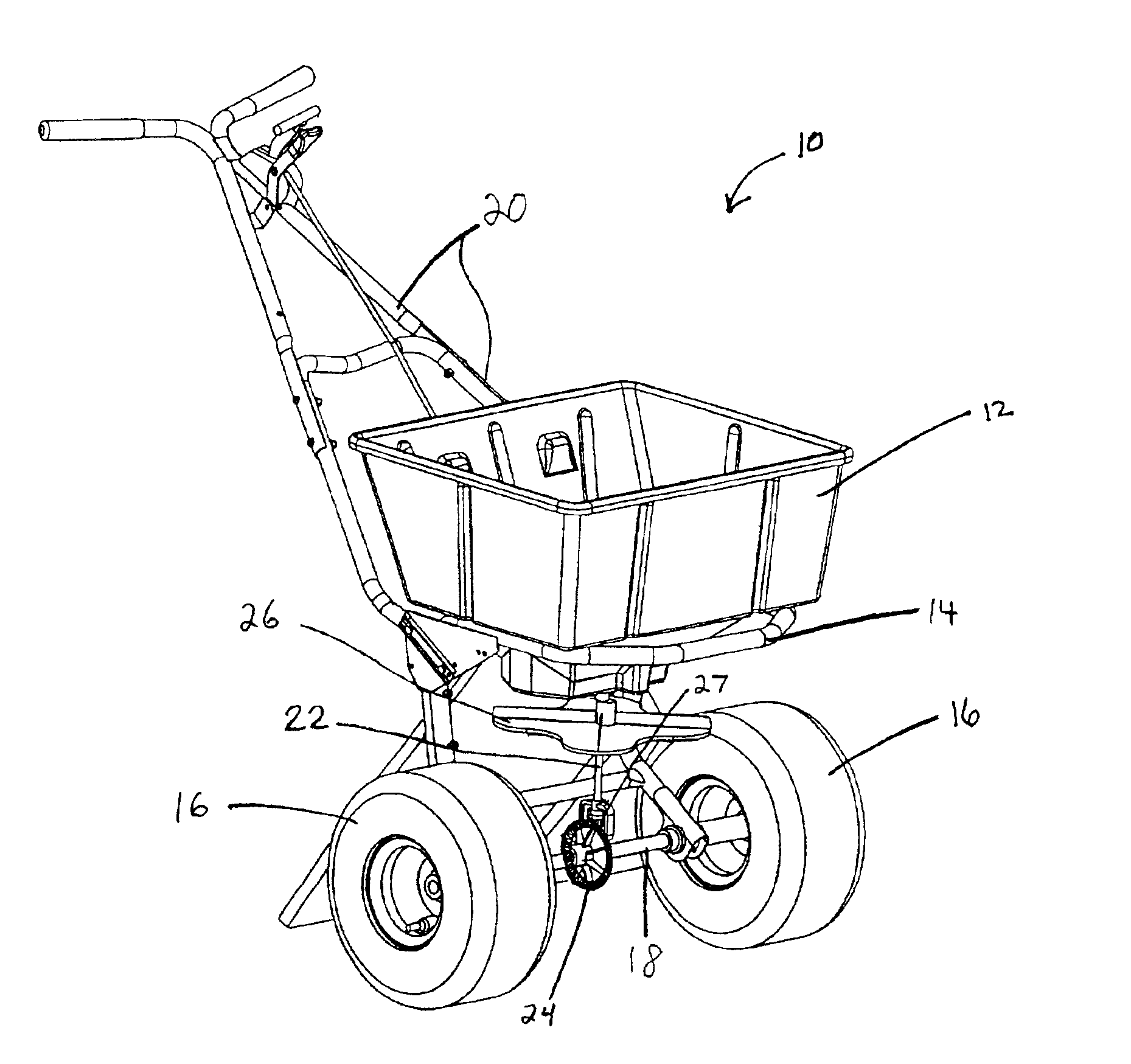
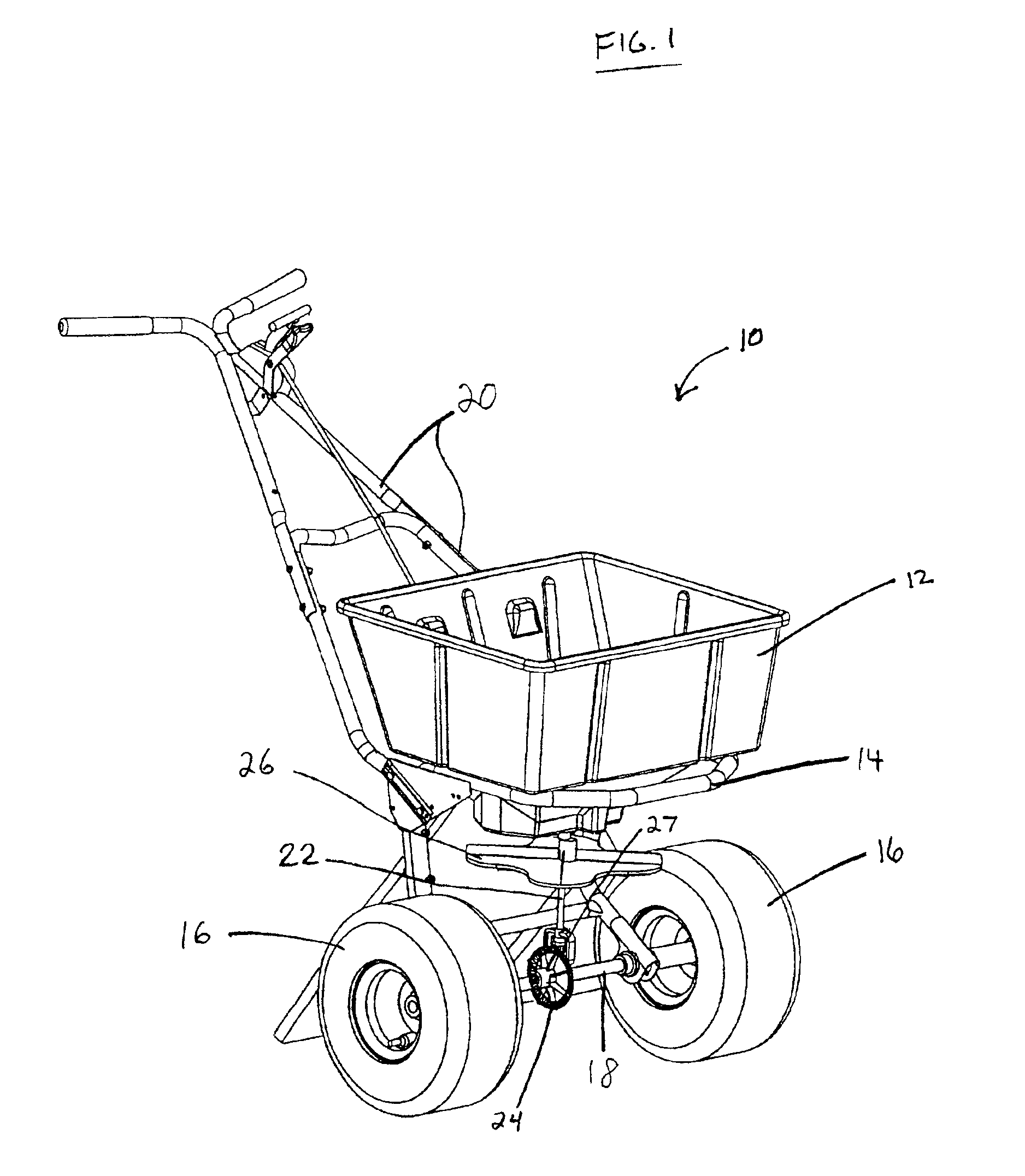
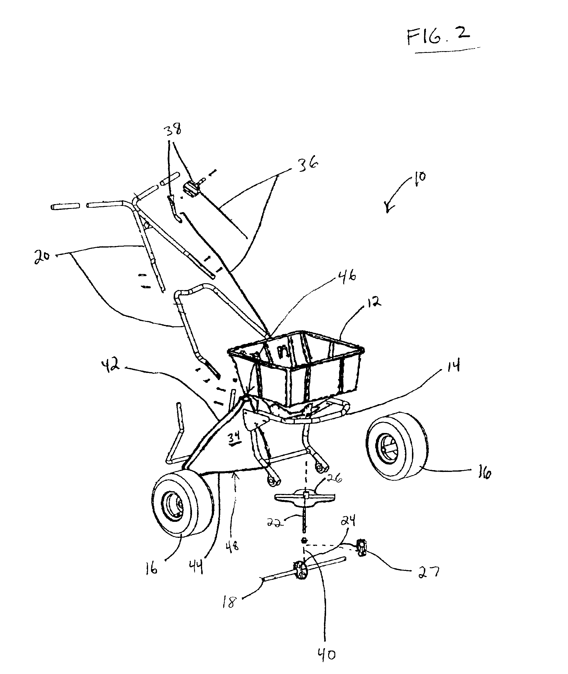
[0022]Referring now to the drawings, the preferred embodiment and best mode of a dual mode spreader, generally designated 10, is shown in FIG. 1. As best shown in FIG. 2, the spreader 10 comprises a hopper 12, for holding a supply of spreadable material, mounted to a frame 14. Frame 14 is connected to a pair of ground-engaging wheels 16 via axle 18. Frame 14 is also connected to handle 20 to enable a user to manually propel the hopper 12 over a selected ground area by rolling the wheels 16 along the ground.

[0023]The dual mode spreader is preferably made almost entirely of molded plastics so as to be generally lightweight, corrosion resistant, durable, and easy to manufacture, transport and assemble. It is understood, however, that any appropriate materials can be used to construct any of the structures of the spreader 10.

[0024]One or both wheels 16 are fixedly connected to axle 18 for transmitting power to vertical shaft 22 by means of a first bevel gear 24 fixedly mounted on axle 1...


PUM


Abstract

A dual mode spreader for broadcast spreading and drop spreading material comprising a hopper to hold a supply of spreadable material, first and second discharge openings located within the hopper for which spreadable material can flow therethrough, an impeller mounted in a position below the hopper for rotational movement about an upright axis, wherein the first discharge opening leads to impeller to enable the spreadable material in the hopper to exit therefrom onto the impeller to be distributed in a path outwardly therefrom onto the surface to be treated; and a diffuser defining an inlet opening and an outlet opening, wherein the second discharge opening is in communication with the inlet opening to enable the spreadable material in the hopper to enter the diffuser and exit therefrom through the outlet opening to be distributed in a path downwardly therefrom onto the surface to be treated.

Description

FIELD OF INVENTION[0001]The present invention relates generally to a device for distributing a spreadable material over a selected ground area, and more particularly, to dual mode spreader that can distribute spreadable material in both a broadcast mode to distribute the material outwardly from the spreader in a less controlled pattern over a relatively wide area and a drop mode to release the material downwardly from the spreader in a controlled pattern over a narrower area.BACKGROUND OF THE INVENTION[0002]It is well known in the art to use material spreader devices to distribute all types of spreadable material over a selected ground area. Such material spreader devices distribute fertilizers, pesticides, seeds, ice melters, salt, or other materials in particulate or finely divided form over a selected ground area. Generally, material spreaders known in the art can be classified in two general categories: broadcast spreaders and drop spreaders.[0003]Broadcast spreaders generally d...

Claims


Application Information

Patent Timeline
Patent Type & Authority Patents(United States)
IPC IPC(8): A01C7/08A01C17/00
CPCA01C7/08A01C17/001A01C15/02A01C7/163
Inventor THOMPSON, PETER G.HURTO, KIRK A.PRINSTER, MARK G.
Owner USG STAMFORD BRANCH
Why Eureka
Try Eureka