Load binder

Active Publication Date: 2005-09-20
PEERLESS CHAIN COMPANY
View PDF7 Cites 21 Cited by
  • Summary
  • Abstract
  • Description
  • Claims
  • Application Information

AI Technical Summary

Benefits of technology

[0008]In a preferred embodiment of the invention, the ratchet mechanism as described above is modified to provide the previous two position settings of the mechanism and alternate in-and-out pawl engagement but having a third position where the pawl can be parked in non-engagement position. Thus, where lever force is required to either extend the s

Problems solved by technology

Each log is very heavy and inadvertent rolling of the log off the load can produce disastrous results and is to be avoided.
Not only is the tightening effect limited, the substantial energy stored by such over-cent

Method used


Image

  • Load binder
  • Load binder
  • Load binder

Examples


Embodiment Construction

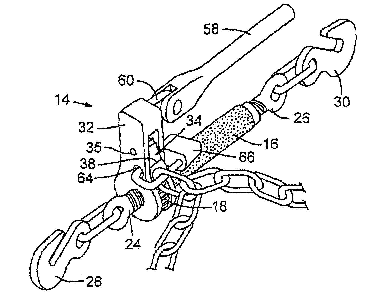
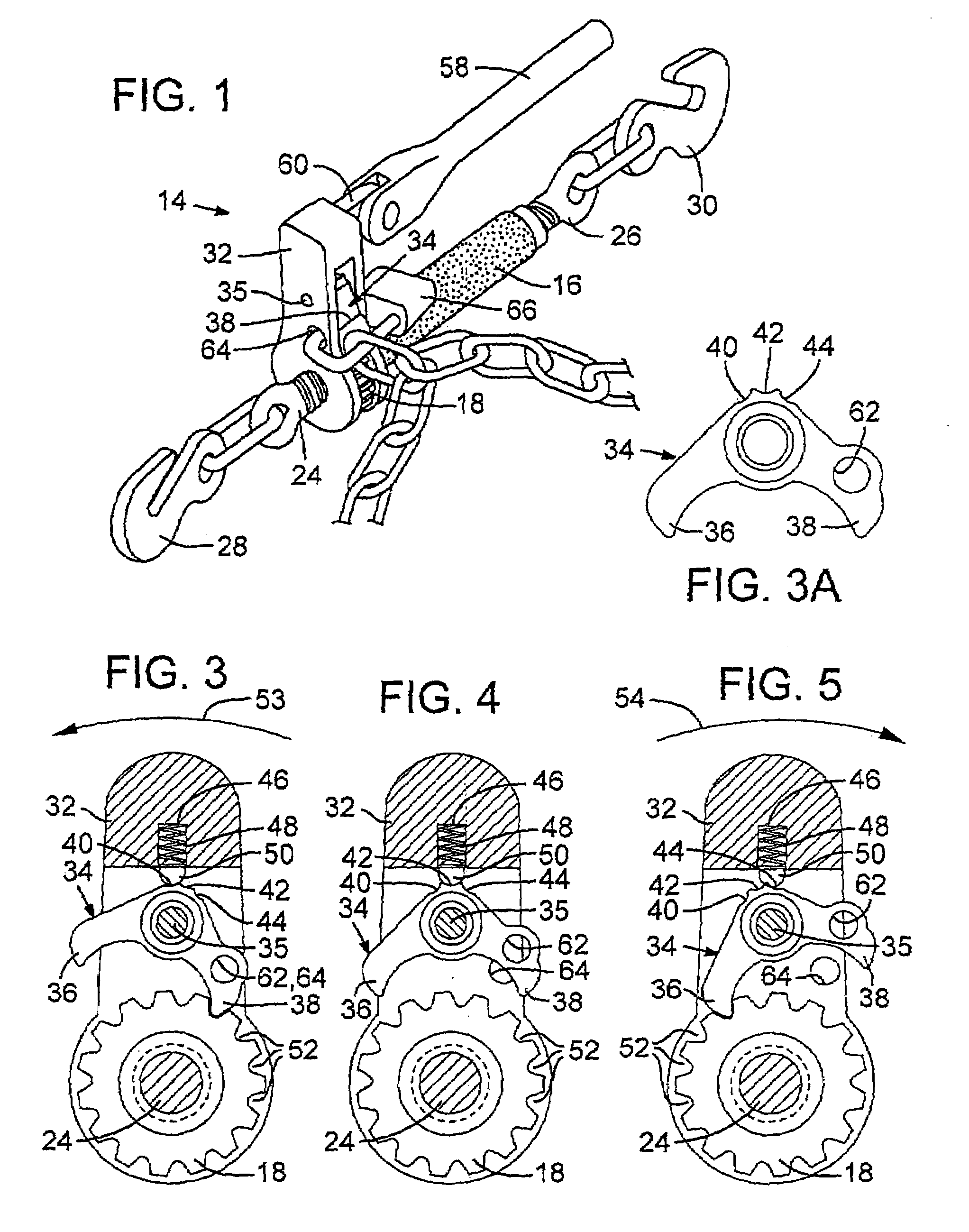
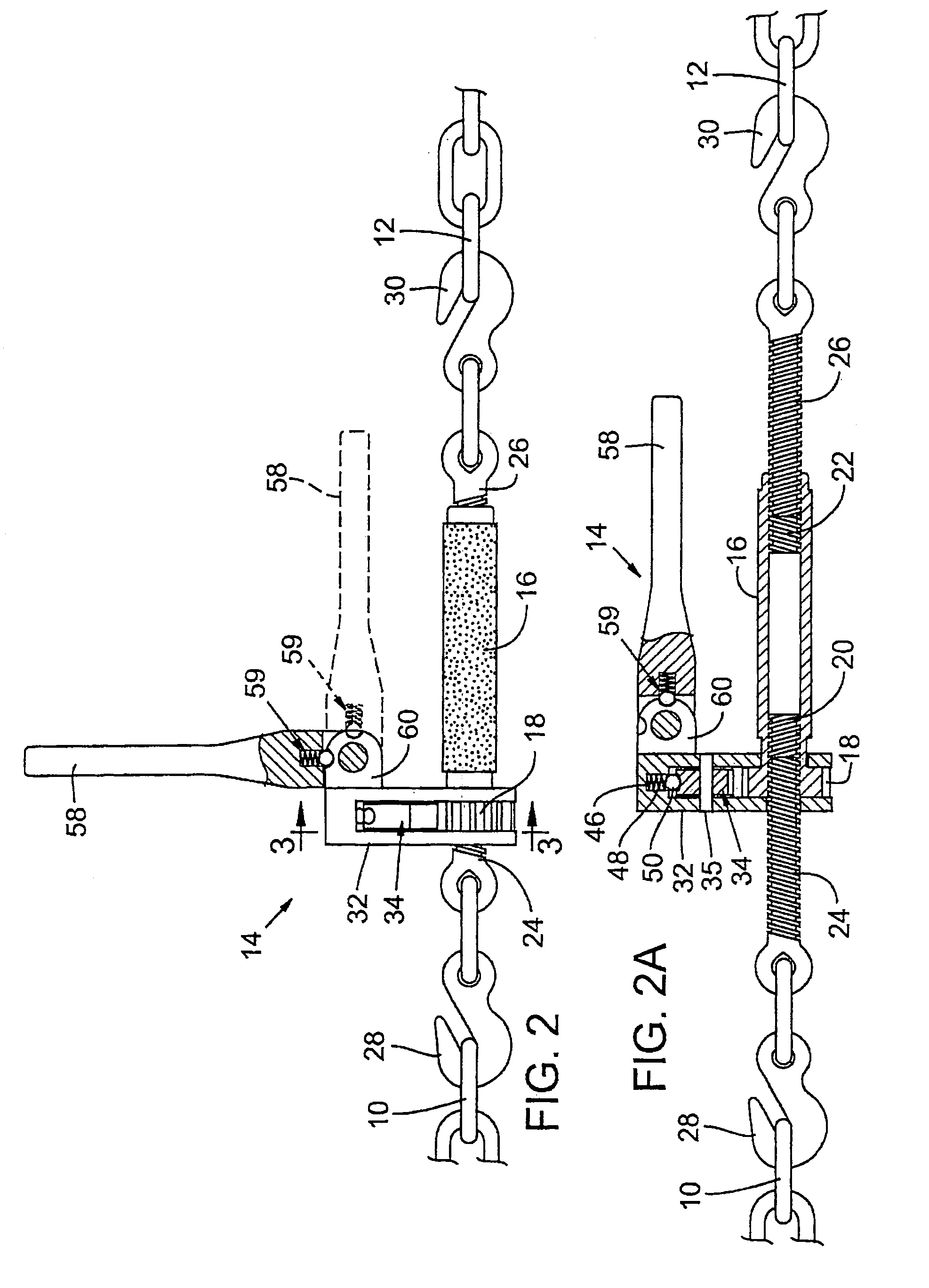
[0015]Reference is first made to FIG. 2A which illustrates the operation of a ratchet load binder in accordance with the present invention. Chain links 10 and 12 represent spaced apart links, e.g. of a length of chain wrapped around a load, e.g. of logs loaded on a logging truck. Whereas FIGS. 2 and 2A do not show a continuum of the chain links, i.e. links 10 and 12 interconnected by a sequence of links, it is most common to simply connect hooks 28, 30 at the most convenient position along the chain length and drawing of links 10 and 12 together produces a loosening of the intermediate links and it is these links that provide the loosened loop of chain for locking the chain to the ratchet mechanism as seen in FIG. 1 and which will be explained hereafter. Returning now to the description of the ratchet hook binder, device 14 includes a tube 16 with a ratchet gear 18 fixedly secured (as by welding) to one end of the tube 16. Tube 16 is threaded at its inner side with left handed threa...


PUM


Abstract

A tool for binding and securing the binding of a load, said binding including a tube having left and right hand threads at opposed ends and sides and threaded shafts mated to the threads whereby turning of the tube relative to the shafts produces common insertion or extension of the shafts relative to the tube. A gear secured to the tube and a pivotal housing with handle surrounding the gear. A pawl carried by the housing and moveable into and out of engagement with the gear in either rotative direction whereby handle movement either contracts or extends the shafts simultaneously from the tube. A centered position of the pawl and a detent in said pawl engaged by a spring biased pinion that retains the pawl as desired out of engagement with the gear for free turning of the tube. The handle may be pivoted to a parallel position with the tube for convenient storage and safety, and a lock may be applied to lock the pawl in a position for contracting the shafts to prevent inadvertent release from the load binding condition.

Description

FIELD OF THE INVENTION[0001]This invention relates to a mechanical device used to tighten and secure bindings such as a link chain being used to stabilize and secure heavy cargo or equipment on a cargo carrying vehicle or vessel including trucks, trains, planes and ships.BACKGROUND OF INVENTION[0002]There are numerous examples that can be cited to explain how items are loaded e.g. on flatbed trailers, rail cars, boat decks and the like. All have a common problem that will be here addressed as that problem relates to the loading and hauling of logs by a logging truck. Such is but one example and those skilled in the art will understand that the invention is equally applicable to many other load hauling uses.[0003]Different sizes of logs, e.g., 10–20 inches in diameter and 20–30 feet in length, are commonly hauled from a forest site to a logging mill. The truck traverses rough roads and many curves that produce conditions where the logs can roll off of the truck bed. Each log is very ...

Claims


Application Information

Patent Timeline
IPC IPC(8): B21F9/00B61D45/00B60P7/06B66F3/00F16G11/00F16G11/12B25B13/46B25B25/00B60P7/08
CPCB60P7/083B60P7/0861B61D45/00
Inventor SCOTT, GARYJULL, KEITHSTOLIN, LOREN
Owner PEERLESS CHAIN COMPANY
Why Eureka
Try Eureka