
Light irradiating unit

Inactive Publication Date: 2005-09-20
MITSUBISHI CHEM CORP
View PDF10 Cites 20 Cited by
  • Summary
  • Abstract
  • Description
  • Claims
  • Application Information

AI Technical Summary

Benefits of technology

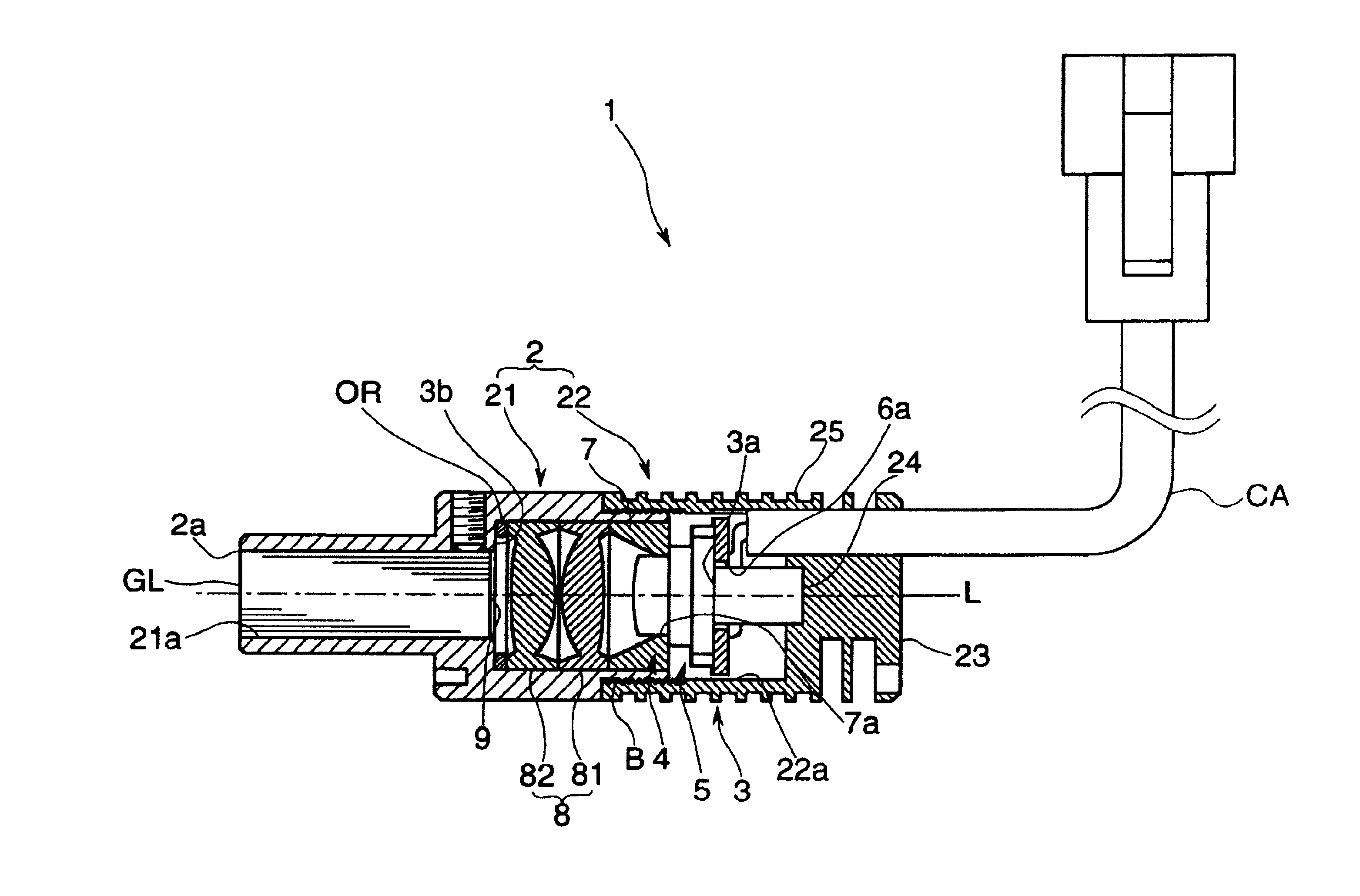
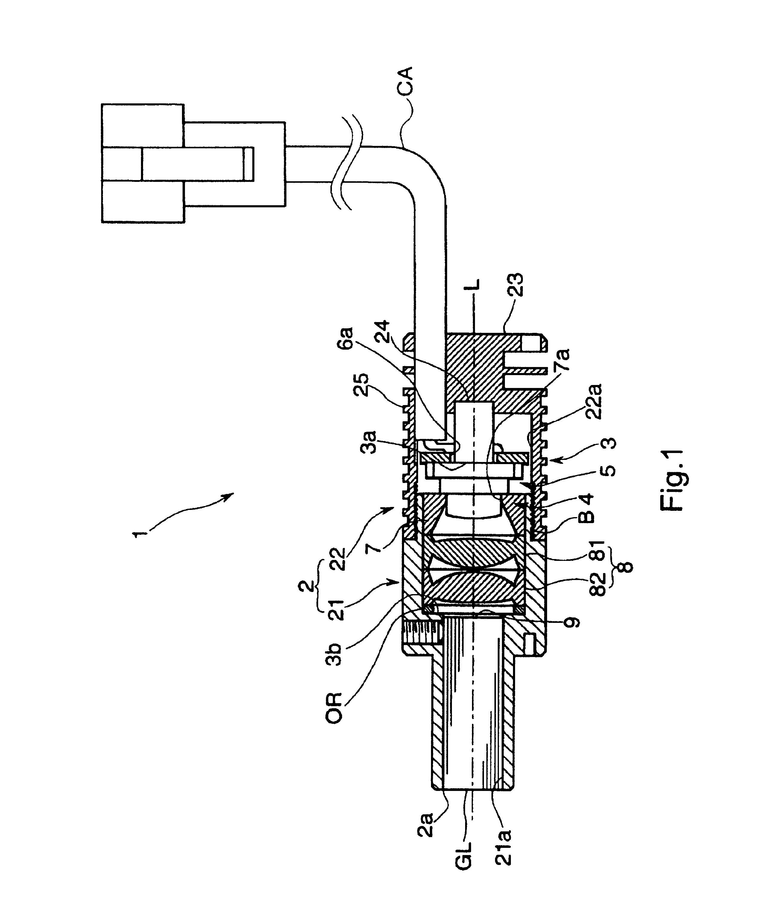
[0009]In accordance with the arrangement, a process of fixing the LED with pressure by the pressing arrangement and a process of positioning the LED by the positioning arrangement are conducted at once when the first housing element is joined to the second housing element. As a result, it is possible to simplify an assembling of the light irradiating unit and to set the light irradiated from the LED with accuracy. In addition, since the LED makes a tight contact with the housing having the heat dissipating portion directly or indirectly through some sort of an intervening member, it is possible to dissipate heat extremely effectively without making a size of the housing unnecessarily bulky. For example, silicone grease may be applied as the intervening member that is a thermal conduction member that improves adhesiveness and heat conductivity by absorbing roughness of the faces between each pressing faces and the LED.
[0015]In this case if an inner face of the ring portion is a mirror finished conic concave face and the ring portion has a function to guide light forward, the positioning arrangement serves also as a function of light reflecting function, thereby to reduce a number of components and to simplify an arrangement.
[0016]In addition, if the light irradiating unit further comprises a lens mechanism that is incorporated into the housing and is so arranged that the light irradiated from the LED is focused on a light focusing portion arranged at a predetermined portion in a size of a predetermined radius through the lens mechanism, a light introducing end portion of a light guiding member such as optical fibers (a bunch) or a glass rod can be arranged at the light focusing portion and light can be effectively irradiated from a light irradiating end of the light guiding member.
[0017]For a light irradiating unit that further comprises a lens mechanism incorporated into the housing, in order to form the positioning arrangement by making use of the lens mechanism and to reduce a number of components without difficulty so as to simplify an arrangement, it is preferable that the positioning arrangement is so arranged to position the LED by inserting the LED without a slack into a concave portion arranged on a lens constituting the lens mechanism.

Problems solved by technology

In addition, since the LED makes a tight contact with the housing having the heat dissipating portion directly or indirectly through some sort of an intervening member, it is possible to dissipate heat extremely effectively without making a size of the housing unnecessarily bulky.

Method used


Image

  • Light irradiating unit
  • Light irradiating unit
  • Light irradiating unit

Examples


first embodiment

[0027]the present claimed invention will be described with reference to the drawings.

[0028]A light irradiating unit 1 in accordance with the embodiment comprises, as shown in FIG. 1, an LED 5 in an elementary substance and a housing 2 into which the LED 5 is incorporated and that has a heat dissipating fin 25 as a heat dissipating portion. The light irradiating unit 1 irradiates light irradiated from the LED 5 through a light irradiating exit 2a arranged on an end face of the housing 2.

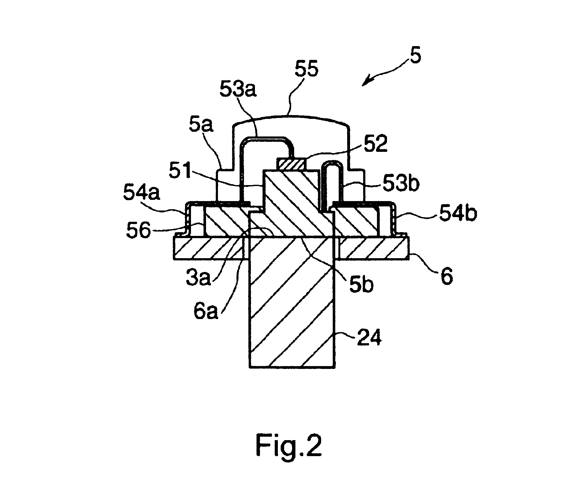
[0029]The LED 5 comprises, as shown in FIG. 2, an electric conductor 51 that also serves as a heat conductor made of metal (for example, copper), a single LED chip 52 that is fixed to the electric conductor 51 with a die bonding or the like, a resin frame 56 that supports the electric conductor 51 by inserting over the electric conductor 51, two pieces of lead wires 53a, 53b (also called as bonding wires) each of whose one end is connected to an electrode of a cathode side (not shown in drawings) or a...

second embodiment

[0043]the present claimed invention will be explained with reference to FIG. 4 and FIG. 5.

[0044]A light irradiating unit 1A in accordance with the second embodiment is, as shown in FIG. 4, so arranged that an LED 5A is incorporated into a housing 2A and like the above mentioned first embodiment comprises a pressing mechanism 3A that fixes the LED 5A with pressure between a first pressing face 3bA arranged at the first housing element 21A side and the second pressing face 3aA arranged at the second housing element 22A side accompanied by joining the first housing element 21A to the second housing element 22A and a positioning arrangement 4A that positions the LED 5A so as to align an optical axis of light irradiated from the LED 5A with a center axial line AL as a predetermined axial line accompanied by joining the first and the second housing element 21A, 22A.

[0045]Each components will be explained with clarifying differences between the light irradiating unit 1 of the first embodim...


PUM


Abstract

A light irradiating unit comprises an LED 5 and a housing 2 into which the LED 5 is incorporated and that has a heat dissipating portion wherein the housing 2 has a first housing element 21 and a second housing element 22 each of which is joined serially along a predetermined axial line, and further comprises a pressing arrangement 3 that fixes the LED 5 with pressure between a first pressing face 3b arranged at the first housing element 21 side and a second pressing face 3a arranged at the second housing element 22 side accompanied by joining the first and the second housing elements 21, 22 and a positioning arrangement 4 that positions the LED 5 so as to align an optical axis of the LED 5 with the predetermined axial line accompanied by joining the first and the second housing elements 21, 22.

Description

BACKGROUND OF THE INVENTION AND RELATED ART STATEMENT[0001]The present claimed invention relates to a light irradiating unit, more specifically to a light irradiating unit that is preferably used to inspect an appearance or a flaw of a product by irradiating light in a factory or the like.[0002]Conventionally, a halogen lamp is used as a light source for this kind of a light irradiating unit. Considering an efficiency or an accuracy in product inspection, however, the halogen lamp as a light source is not suitable to get enough stability in luminous intensity, life duration and a quick responsive characteristics. A plurality of LEDs are used as a new light source to solve this problem. More specifically, generally known is like a light irradiating unit that the present claimed inventor has invented and shown in Japan Patent Laid Open No. 2000-21206 in which a plurality of LEDs are arranged on a print substrate and light is introduced by the plurality of LEDs through a bunch of optic...

Claims


Application Information

Patent Timeline
IPC IPC(8): F21V29/00G01N21/88G02B6/42
CPCF21V19/0035F21V29/004G01N21/8806F21V29/767G02B6/4204G02B6/4296G02B6/4298G02B6/4201F21Y2101/02G02B6/4256G02B6/4269F21Y2115/10F21V29/74
Inventor YONEDA, KENJISUGITA, TAKASHIMIURA, KENJIMASUMURA, SHIGEKI
Owner MITSUBISHI CHEM CORP
Learn More