Micro surgical instrument

a micro-surgical and instrument technology, applied in the field of micro-surgical instruments, can solve the problems of trauma or injury to these delicate blood vessels, obstruction of blood flow, artery or vein injury, etc., and achieve the effect of easy retention and grasping of micro-structures, easy and free retention and holding

Inactive Publication Date: 2005-09-20
ALCON INC
View PDF13 Cites 48 Cited by
  • Summary
  • Abstract
  • Description
  • Claims
  • Application Information

AI Technical Summary

Benefits of technology

[0006]According to one aspect of the present invention an improved ophthalmologic instrument is provided which is designed to obviate the afore-stated shortcomings and which is configured for retaining these delicate blood vessels by providing an instrument for easy retention and grasping of the microstructures.
[0007]In another aspect, the present invention provides an improved ophthalmologic instrument with two grasping arms that permit freely holding delicate micro structures such as blood vessels or similar.
[0008]These aspects, and others which will become apparent hereinafter, are attained in accordance with the present invention, wherein the microsurgical instrument has a probe attached with a rod axially disposed therein, the rod has a head piece from which two arms extend in axial direction which are separated by a slot and which can be spread apart relative to each other for a spring elastic pretensioning. At their respective front ends, the arms are so configured that when moving the arms toward each other in a closing motion, a recess is formed which is dimensioned perpendicular relative to the rod axis in which recess a microstructure such as a blood vessel can be easily and freely retained and held.

Problems solved by technology

In the area of the crossing the artery and the vein are surrounded by a substantially transparent skin sheath or membrane and the artery which overlays the vein can press on the vein such that the vein may be squeezed off in such a manner that an occlusion occurs resulting in an obstruction of the blood flow.
When using the conventional microsurgical instruments separation of the artery from the vein may result in the injury to the artery or injury to the underlying vein.
Furthermore, the artery may be “pinched” by the microsurgical instrument during separation leading to trauma or injury of these delicate blood vessels.

Method used


Image

  • Micro surgical instrument
  • Micro surgical instrument
  • Micro surgical instrument

Examples


Embodiment Construction

[0030]Throughout all the Figures, same or corresponding elements are generally indicated by same reference numerals.

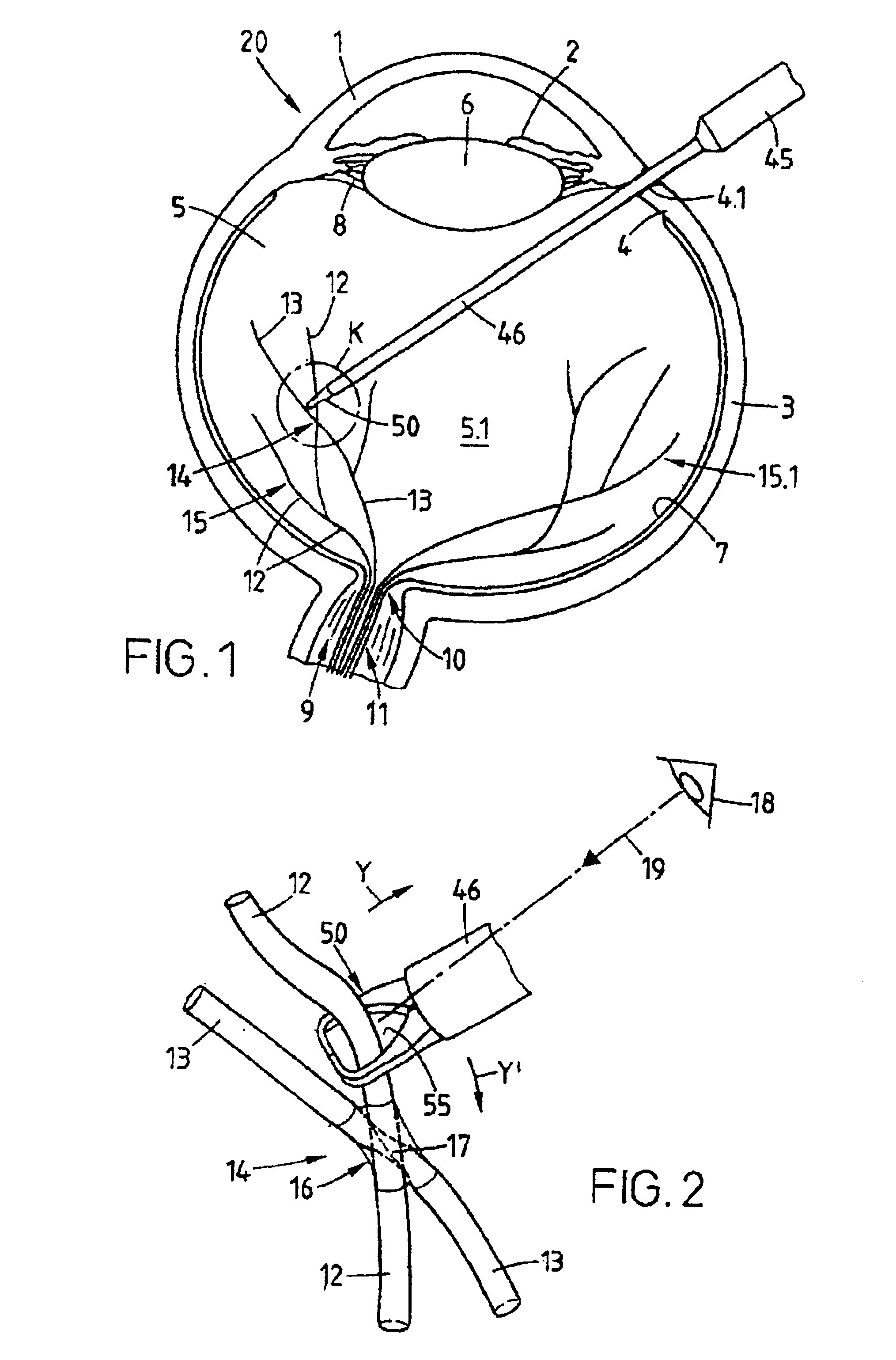
[0031]Turning now to the drawing, and in particular to FIG. 1, there is shown in a schematic horizontal section on an enlarged scale a human eye, generally designated by reference numeral 20 and including the cornea 1, the iris 2, the sclera 3, the pars plana 4, the vitreous humor 5 with its vitreous chamber 5.1, the lens 6, the retina 7, the ciliary processes 8, (zonule fibers). In the eye background the disc shaped optic disk 10 is shown where the nerve fibers of the retina are gathered into the optic nerve bundle 9 from where they leave the eye.

[0032]The central artery and venous system generally designated with 11 which is surrounded by the optic nerve bundle 9 branches into several branches in the optical disc 10 jointly forming the two blood vessel systems 15 and 15.1. The blood vessel system 15 which is schematically depicted in FIG. 1 comprises the arteries 12 ...


PUM


Abstract

A microsurgical instrument is described for ophthalmologic microsurgery in the eye which comprises a housing configured as a handle with a functional unit supporting a probe and a rod co-axially supported in the probe having a head piece configured as a grasping element with two arms that can be brought into a spread apart first position and a second closed position, wherein each arm has a recess which upon closing are flush pressed together thereby forming a larger recess for unobstructed grasping, retaining and holding microstructures such as blood vessels without squeezing or pinching the microstructures.

Description

BACKGROUND OF THE INVENTION[0001]The present invention relates to a microsurgical instrument, in particular to a ophthalmologic instrument for use especially but not exclusively in surgery of the retina of an eye of the type having a housing configured as a handle and an axial probe operatively connected to the housing, wherein the probe is configured for receiving an axially extended rod with a head piece configured for microsurgical procedures.[0002]The present invention concerns problems that arise in surgical treatment of retinal diseases, as for example resulting from hypertonia, or other vascular changes. In a typical disease where vascular changes are the origin, a venous branch occlusion (phlebemphraxis) can occur at the crossing point of an artery and a vein. In the area of the crossing the artery and the vein are surrounded by a substantially transparent skin sheath or membrane and the artery which overlays the vein can press on the vein such that the vein may be squeezed ...

Claims


Application Information

Patent Timeline
Patent Type & Authority Patents(United States)
IPC IPC(8): A61B17/28A61B17/30A61B19/00A61F9/007
CPCA61B17/29A61B17/30A61B17/2909A61B2017/2937A61B2019/5206A61F9/007A61B2017/305A61B2090/306
Inventor ARUMI, JOSE GARCIAMAAG, WERNERJUD, OLIVER
Owner ALCON INC
Why Eureka
Try Eureka