Intervertebral implant with deformable wedge

a technology of intervertebral implants and wedges, which is applied in the field of intervertebral implants, can solve the problems that the wedges are an obstacle to the movement of vertebrae, and achieve the effect of simplifying manufacturing

Inactive Publication Date: 2005-09-20
ZIMMER SPINE INC
View PDF7 Cites 473 Cited by
  • Summary
  • Abstract
  • Description
  • Claims
  • Application Information

AI Technical Summary

Benefits of technology

[0028]In a second aspect, the invention provides a method of manufacturing an intervertebral implant, in particular of the above defined type, which method simplifies manufacture. This result is achieved due to the fact that the wedge of the implant is made by injection molding a polymer.

Problems solved by technology

The wedge therefore constitutes an obstacle to movement the vertebrae towards each other.

Method used


Image

  • Intervertebral implant with deformable wedge
  • Intervertebral implant with deformable wedge
  • Intervertebral implant with deformable wedge

Examples


first embodiment

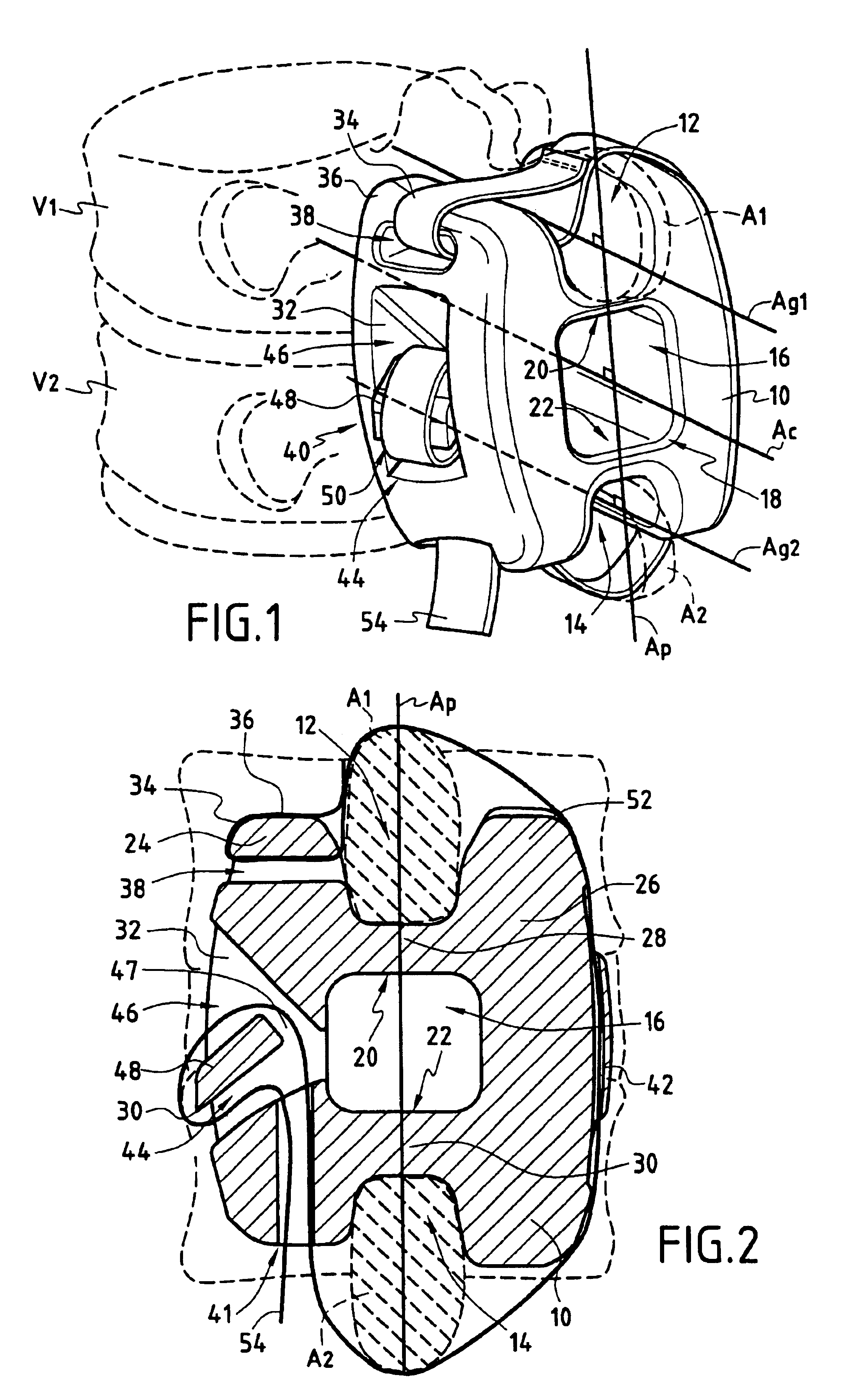
[0033]the intervertebral implant according to the invention is described first with reference to FIG. 1.

[0034]FIG. 1 shows two consecutive vertebrae V1 and V2 extended in their posterior part by respective spinous processes A1 and A2. A wedge 10 having a top groove 12 and a bottom groove 14 is inserted between the spinous processes A1 and A2 so that to processes A1 engages in the groove 12 and the process A2 engages in the groove 14. The top groove 12 and bottom groove 14 have respective and substantially parallel axes Ag1 and Ag2.

[0035]The wedge 10 has a central opening 16 between the two grooves 12 and 14; the opening is of substantially rectangular parallelepiped shape and passes completely through said wedge 10. For practical reasons concerning the manufacture of said wedge 10, the corners 18 of the opening are rounded throughout the thickness of the wedge.

[0036]The central opening has an axis Ac substantially parallel to the axes Ag1 and Ag2 of the top groove 12 and the bottom ...

second embodiment

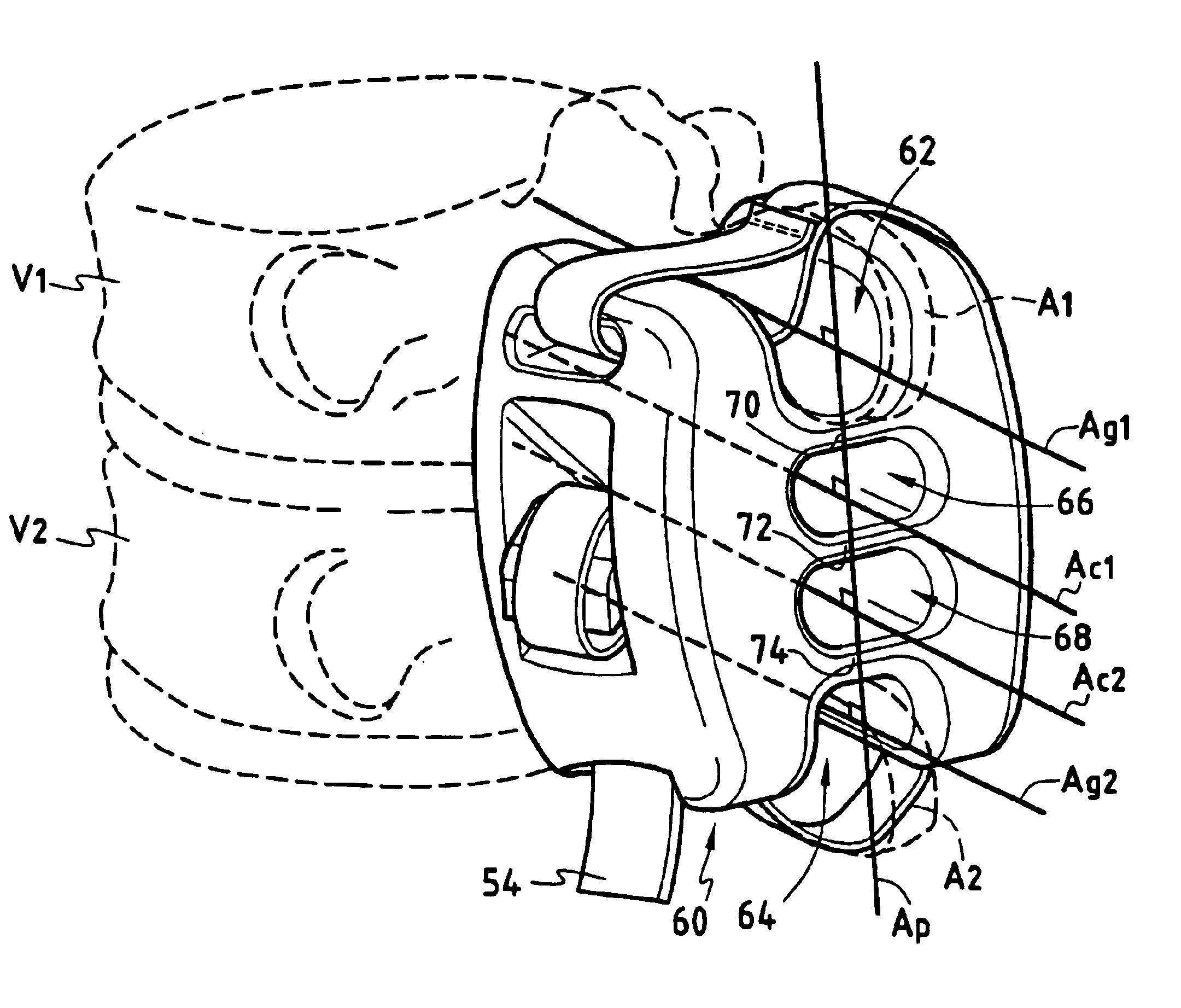
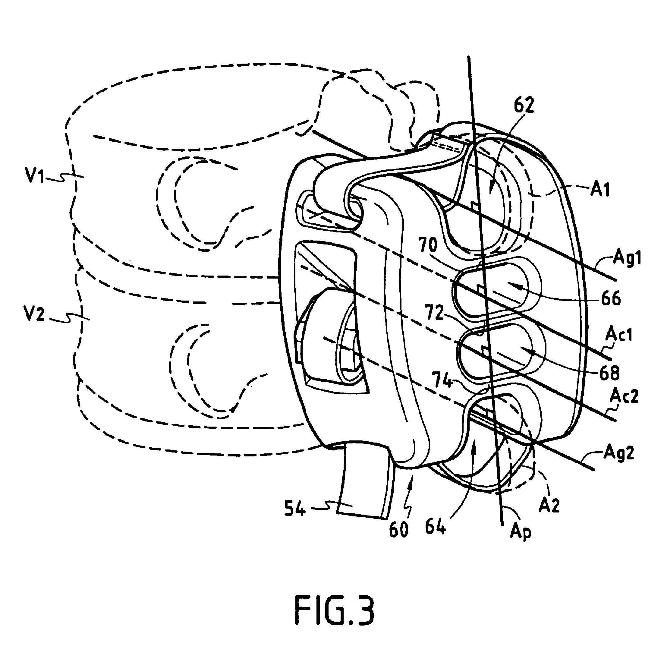
[0056]an intervertebral implant in which the wedge has two openings is described next with reference to FIG. 3.

[0057]FIG. 3 shows a wedge 60 between two vertebrae V1 and V2 which are extended by respective spinous processes A1 and A2 which engage in a top groove 62 and a bottom groove 64 of the wedge 60. The wedge is connected to the spinous processes by a fixing band in a similar manner to the wedge 10 shown in FIGS. 1 and 2.

[0058]The wedge 60 has two superposed opening 66 and 68 with respective axes Ac1 and Ac2 substantially parallel to each other and to the axes Ag1 and Ag2 of said grooves 62 and 64. The superposed openings 66 and 68 have a shape including two parallel superposed faces and two facing curved walls.

[0059]Thus the wedge 60 is divided into two parts joined together by three partitions 70, 72 and 74 adapted to deform when a force is exerted on the wedge 60. Obviously, the capacities for deformation of the wedge 60 are less than that of the wedge 10 shown in FIGS. 1 an...


PUM

PropertyMeasurementUnit
volumeaaaaaaaaaa
total volumeaaaaaaaaaa
shapeaaaaaaaaaa

Abstract

The invention relates to an intervertebral implant including a wedge which is inserted between two spinous processes and has two opposite grooves in which said spinous processes engage, which grooves have substantially parallel axes, and each of which grooves is defined by two flanges. The wedge has at least one central opening between said two grooves and said central opening passes completely through said wedge along an axis Ac substantially parallel to the axes Ag1 and Ag2 of said grooves, which renders said wedge elastically deformable.

Description

CROSS-REFERENCE TO RELATED APPLICATIONS[0001]Not ApplicableSTATEMENT REGARDING FEDERALLY SPONSORED RESEARCH OR DEVELOPMENT[0002]Not ApplicableINCORPORATION-BY-REFERENCE OF MATERIAL SUBMITTED ON A COMPACT DISC[0003]Not ApplicableFIELD OF THE INVENTION[0004]The present invention relates to an intervertebral implant including a wedge adapted to be inserted between two spinous processes, said wedge having two opposite grooves each defined by two flanges, the sea of acid two grooves being substantially parallel to each other and said spinous processes engaging in said two groove. The present invention also relates to a method of manufacturing as intervertebral implant, in particular the above defined type.BACKGROUND OF THE INVENTION[0005]Intervertebral implants including a wedge which is inserted between the spinous processes which extend the posterior part of two consecutive vertebrae and which limits movement towards each other of the two vertebrae are well known in the art.[0006]Degen...

Claims


Application Information

Patent Timeline
Patent Type & Authority Patents(United States)
IPC IPC(8): A61B17/70A61B17/58A61F2/44A61L27/00
CPCA61B17/7062Y10S606/91A61B17/70
Inventor SENEGAS, JACQUESPASQUET, DENISLE COUEDIC, REGIS
Owner ZIMMER SPINE INC
Why Eureka
Try Eureka