High-strength high-temperature creep-resistant iron-cobalt alloys for soft magnetic applications

a high-temperature creep-resistant, iron-cobalt alloy technology, applied in the direction of magnetic materials, basic electric elements, magnetic bodies, etc., can solve the problems of undesirable inherent properties of conventional fe—co-v alloys employing less than 2% by weight vanadium, deterioration of energy efficiency of magnetic materials, and unsuitable magnetic properties of conventional fe—co-v alloys, etc., to achieve the effect of breaking down the cast microstructur

Inactive Publication Date: 2005-09-20
PHILIP MORRIS USA INC
View PDF34 Cites 30 Cited by
  • Summary
  • Abstract
  • Description
  • Claims
  • Application Information

AI Technical Summary

Benefits of technology

[0023]A preferred method comprises forging or rolling the alloy at a temperature greater than 1000° C. in order to break down the cast microstructure. Another method comprises cold rolling the alloy, and then annealing the alloy at a temperature in the range of 850 to 1000° C.; water quenching the alloy; and aging the alloy at a temperature in the range of 600 to 700° C., wherein the method is effective in achieving a room temperature yield stress of at least 800 MPa and a room temperature ultimate tensile strength of at least 1000 MPa.

Problems solved by technology

Conventional Fe—Co—V alloys employing less than 2% by weight vanadium, however, have undesirable inherent properties.
For example, when the magnetic material undergoes a large magnetic loss the energy efficiency of the magnetic material deteriorates significantly.
In addition, conventional Fe—Co—V alloys exhibit certain unsuitable magnetic properties when subjected to rapid current fluctuations.
Furthermore, the clamping of the rotor will result in large compressive axial loads while rotation of the rotor can create tensile hoop stresses of approximately 85 ksi.
However, their yield strengths are low at room temperature, and the yield strengths are even lower at high temperatures, making the alloys unsuitable for applications such as magnetic parts for jet engines that impose high temperatures and centrifugal stress on materials.

Method used


Image

  • High-strength high-temperature creep-resistant iron-cobalt alloys for soft magnetic applications
  • High-strength high-temperature creep-resistant iron-cobalt alloys for soft magnetic applications
  • High-strength high-temperature creep-resistant iron-cobalt alloys for soft magnetic applications

Examples


Embodiment Construction

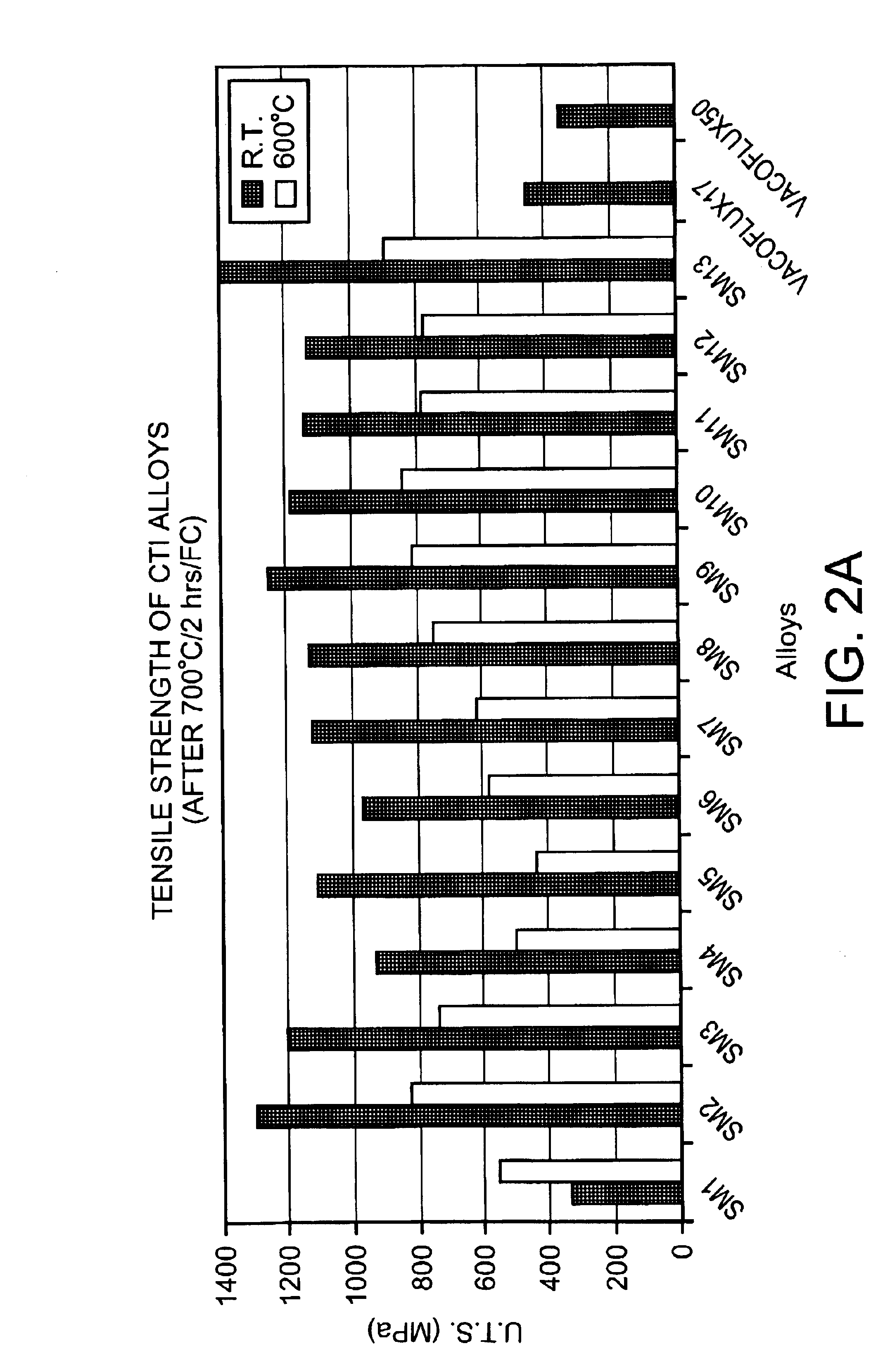
[0037]The invention provides Fe—Co and Fe—Co—V alloys having mechanical and magnetic properties suitable for a number of advanced applications. For example, the tensile and creep strengths at both room temperature and elevated temperature, as well as the high resistivity of the alloys, make them more suitable than conventional soft magnetic alloys for advanced aerospace applications.

[0038]Table 1a provides exemplary compositions in weight percent (and Table 1b provides the compositions in atomic percent) of soft magnetic iron-cobalt (Fe—Co) alloys. For all of the alloys represented in Table 1, iron represents the balance of the composition. SM-1 is analogous to prior art iron-cobalt-vanadium (Fe—Co—V) alloys currently in commercial production whereas samples SM-1a through SM-29 are inventive alloys. There are several general groupings of the alloys based on composition. The first grouping is a cobalt based alloy: SM-2 is an example of such a cobalt based alloy. A second grouping is ...


PUM

PropertyMeasurementUnit
total elongationaaaaaaaaaa
yield strengthaaaaaaaaaa
temperatureaaaaaaaaaa

Abstract

A high strength and creep resistant soft magnetic Fe—Co alloy includes, in weight %, Fe and Co such that the difference between the Fe and Co is at least 2%, at least 35% Co, and 2.5%≦(V+Mo+Nb), wherein 0.4%≦Mo and/or 0.4%≦Nb. This alloy can further include B, C, W, Ni, Ti, Cr, Mn and/or Al. A vanadium-free high strength soft magnetic Fe—Co alloy includes, in weight %, Fe and Co such that the difference between the Fe and Co is at least 2%, and at least 15% Co, the alloy further satisfying (0.1%≦Nb and 0.1%≦W) or 0.25%≦Mn. This alloy can further include B, C, Ni, Ti, Cr and/or Al.

Description

RELATED APPLICATION[0001]This application is a continuation-in-part of U.S. application Ser. No. 09 / 757,625, filed on Jan. 11, 2001 now U.S. Pat. No. 6,685,882.FIELD OF THE INVENTION[0002]This invention relates to high-temperature, high-strength magnetic alloys with high saturation magnetization useful for applications such as rotors, stators and / or magnetic bearings of an auxiliary power unit of an aircraft jet engine.BACKGROUND OF THE INVENTION[0003]In the discussion of the state of the art that follows, reference is made to certain structures and / or methods. However, the following references should not be construed as an admission that these structures and / or methods constitute prior art. Applicant expressly reserves the right to demonstrate that such structures and / or methods do not qualify as prior art against the present invention.[0004]As disclosed in related U.S. application Ser. No. 09 / 757,625, the disclosure of which is incorporated herein by reference, binary iron-cobalt ...

Claims


Application Information

Patent Timeline
Patent Type & Authority Patents(United States)
IPC IPC(8): C22C1/04C22C19/07C22C33/02C22C38/10C22C38/12H01F1/147
CPCB22F2003/248B22F2998/00B22F2998/10C22C1/0433C22C19/07C22C33/0285C22C38/10C22C38/105C22C38/12H01F1/147H01F1/14716B22F5/006C22C1/1084B22F3/115B22F3/18B22F3/24B22F3/10
Inventor DEEVI, SEETHARAMA C.SUNDAR, RANGARAJ S.
Owner PHILIP MORRIS USA INC
Why Eureka
Try Eureka