Integrated and independently controlled transmit only and receive only coil arrays for magnetic resonance systems

a magnetic resonance system and transmit only technology, applied in the field of magnetic resonance imaging, can solve the problems of increasing the complexity of decoupling and phase correction of the coils in the array, the inability to optimize such factors, and the difficulty of powering a single large transmit coil for rapid imaging applications at high field strength

Inactive Publication Date: 2005-09-20
GENERAL ELECTRIC CO
View PDF10 Cites 52 Cited by
  • Summary
  • Abstract
  • Description
  • Claims
  • Application Information

AI Technical Summary

Problems solved by technology

As main field strength has increased, it has become difficult to power a single large transmit coil for rapid imaging applications at high field strength.
The alternative has been to use smaller transceiver coils as part of a coil array, but these have other problems.
Because of coils being used for both transmitting and receiving, there is no means to optimize such factors as field uniformity for both transmitting and receiving.
In addition, decoupling and phase correction of the coils in an array becomes more complicated and difficult.

Method used


Image

  • Integrated and independently controlled transmit only and receive only coil arrays for magnetic resonance systems
  • Integrated and independently controlled transmit only and receive only coil arrays for magnetic resonance systems
  • Integrated and independently controlled transmit only and receive only coil arrays for magnetic resonance systems

Examples


Embodiment Construction

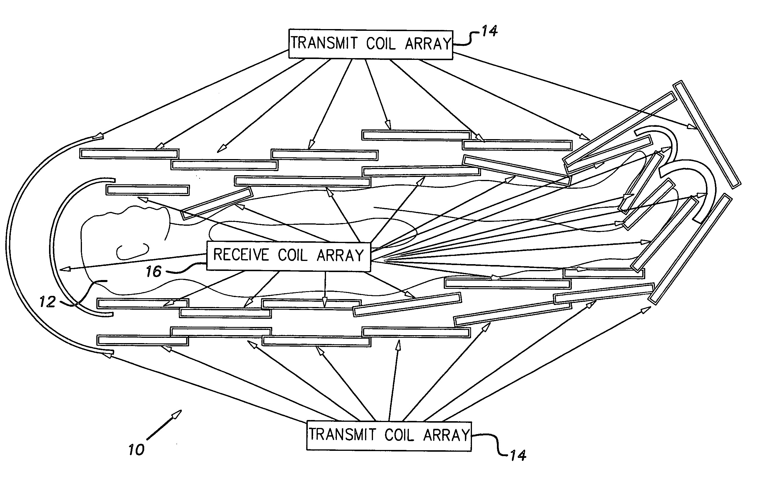
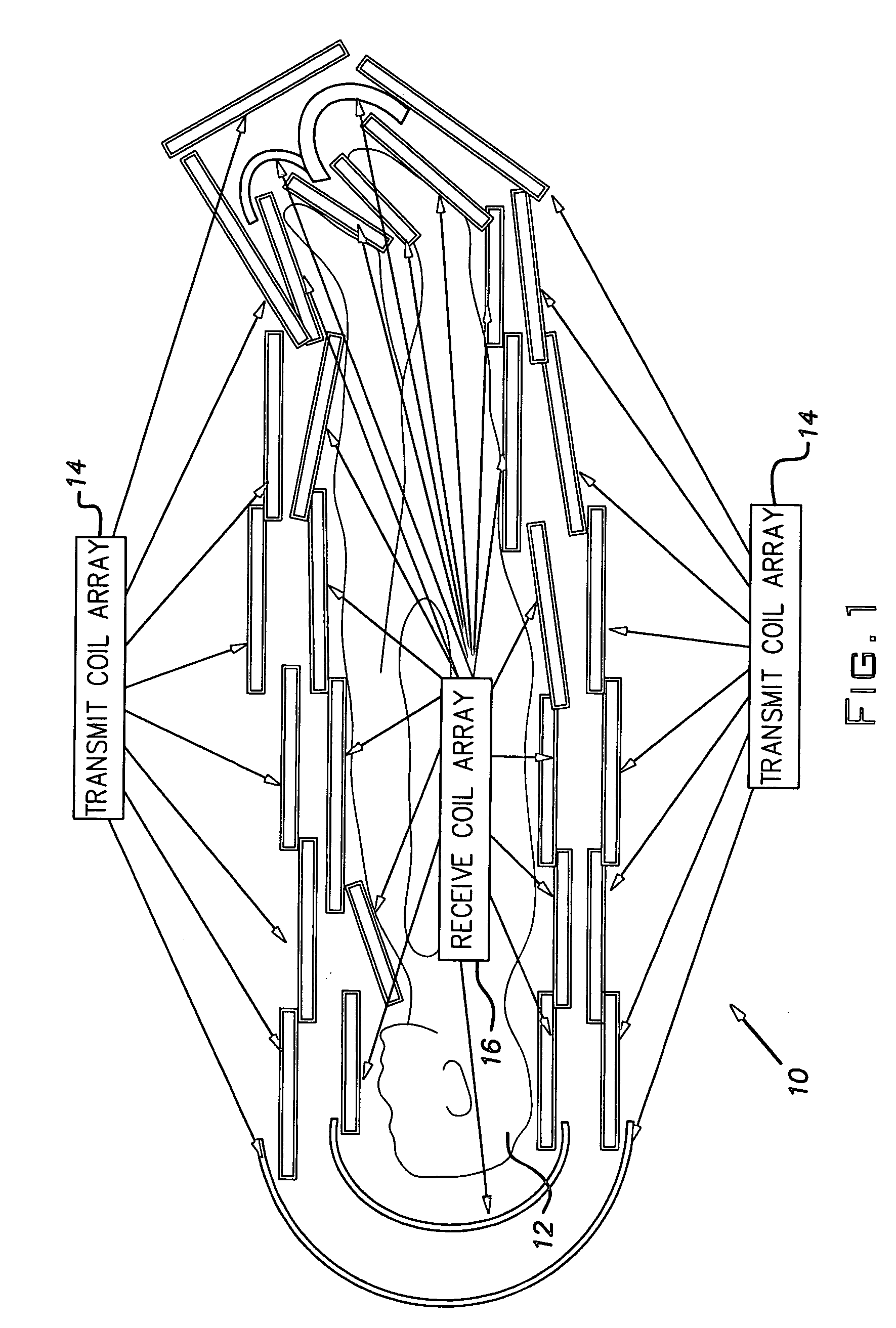
[0018]Referring to FIG. 1, a MRI array coil 10 is shown positioned about the body 12 of a subject. The FOV of the coil 10 can include the whole of the body 12. The transmit coil array 14 and the receive coil array 16 are integrated into a common support structure, which is not shown. The support structure may be, for example, plastic, foam or other suitable materials in such forms, for example, as clamshell, split-top, solid or split into various sections suitable for arranging about the subject. The individual coils may be chosen as linear or quadrature and surface or volume, depending on the desired application. The embodiment of FIG. 1 has a one-to-one correspondence between transmit and receive coils. The transmit coil array 14 and the receive coil 16 are electrically disjoint.

[0019]During transmission selected transmit coils are turned on and all the receive coils are turned off and during receiving selected receive coils are turned on and all of the transmit coils are turned o...


PUM


Abstract

A MRI array coil includes a plurality of first coils in a receive coil array and a plurality of second coils in a transmit coil array. The receive coil array and the transmit coil array are electrically disjoint.

Description

CROSS-REFERENCE TO RELATED APPLICATION[0001]This application claims the benefit of U.S. provisional patent application Ser. No. 60 / 274,523 filed Mar. 8, 2001.BACKGROUND OF THE INVENTION[0002]The present invention relates to magnetic resonance imaging and, in particular, to radio frequency coils.[0003]Radio frequency (RF) coils are used produce and / or sense the magnetic resonance (MR) signal used in magnetic resonance imaging (MRI). A main static magnetic field aligns the nuclei of interest, gradient coils provide indicia of spacial location and the transmit and receive RF coils produce the desired contrast signal.[0004]A MR scanner with a horizontally directed main field will normally have the main field parallel with the scanner's main symmetry plane. These scanners are the original MR scanners.[0005]A MR scanner with a vertically directed main field will normally have the main field orthogonal to the pole surface and to the main magnet's symmetry plane. These scanners are normally...

Claims


Application Information

Patent Timeline
Patent Type & Authority Patents(United States)
IPC IPC(8): G01V3/00G01R33/3415
CPCG01R33/3415
Inventor ZOU, MARK XUEMINGPETROPOULOS, LABROS S.MURPHY-BOESCH, JOSEPHCHAN, PEITHOMAS, RONY
Owner GENERAL ELECTRIC CO
Why Eureka
Try Eureka