Circuit for locking an oscillator to a data stream

a technology of oscillator and data stream, which is applied in the direction of pulse manipulation, pulse technique, instruments, etc., can solve the problems of incompatibility of data communication systems, short data packets, and inability to lock oscillators to data streams

Inactive Publication Date: 2005-09-20
MONTEREY RES LLC
View PDF41 Cites 26 Cited by
  • Summary
  • Abstract
  • Description
  • Claims
  • Application Information

AI Technical Summary

Benefits of technology

[0008]The objects, features and advantages of the present invention include providing a method and / or architecture for locking an incoming data stream that may (i) precisely lock to a rate of the incoming data stream without an external precision timing element (e.g., without crystals, resonators, etc.), (ii) allow incoming data traffic to provide precision timing, (iii) provide multiple tuning phases during a single packet, and / or (iv) tune quickly (e.g., within one data packet).

Problems solved by technology

Such approaches typically require a very long training sequence and / or a continuous stream of data.
Either requirement is incompatible with data communication systems like the Universal Serial Bus (USB), where the data packets can be short and bursty.
Delay Lock Loops and / or Phase Lock Loops can also suffer from the requirement of (i) long training sequences, (ii) requiring continuous input (e.g., cannot handle bursty data), and / or (iii) may need a precision timing component.

Method used


Image

  • Circuit for locking an oscillator to a data stream
  • Circuit for locking an oscillator to a data stream
  • Circuit for locking an oscillator to a data stream

Examples


Embodiment Construction

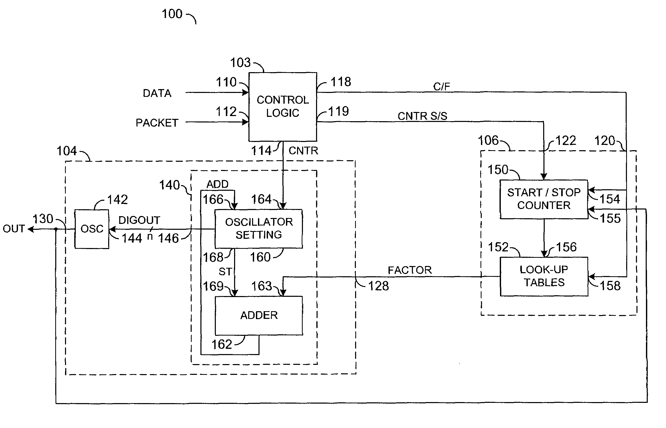
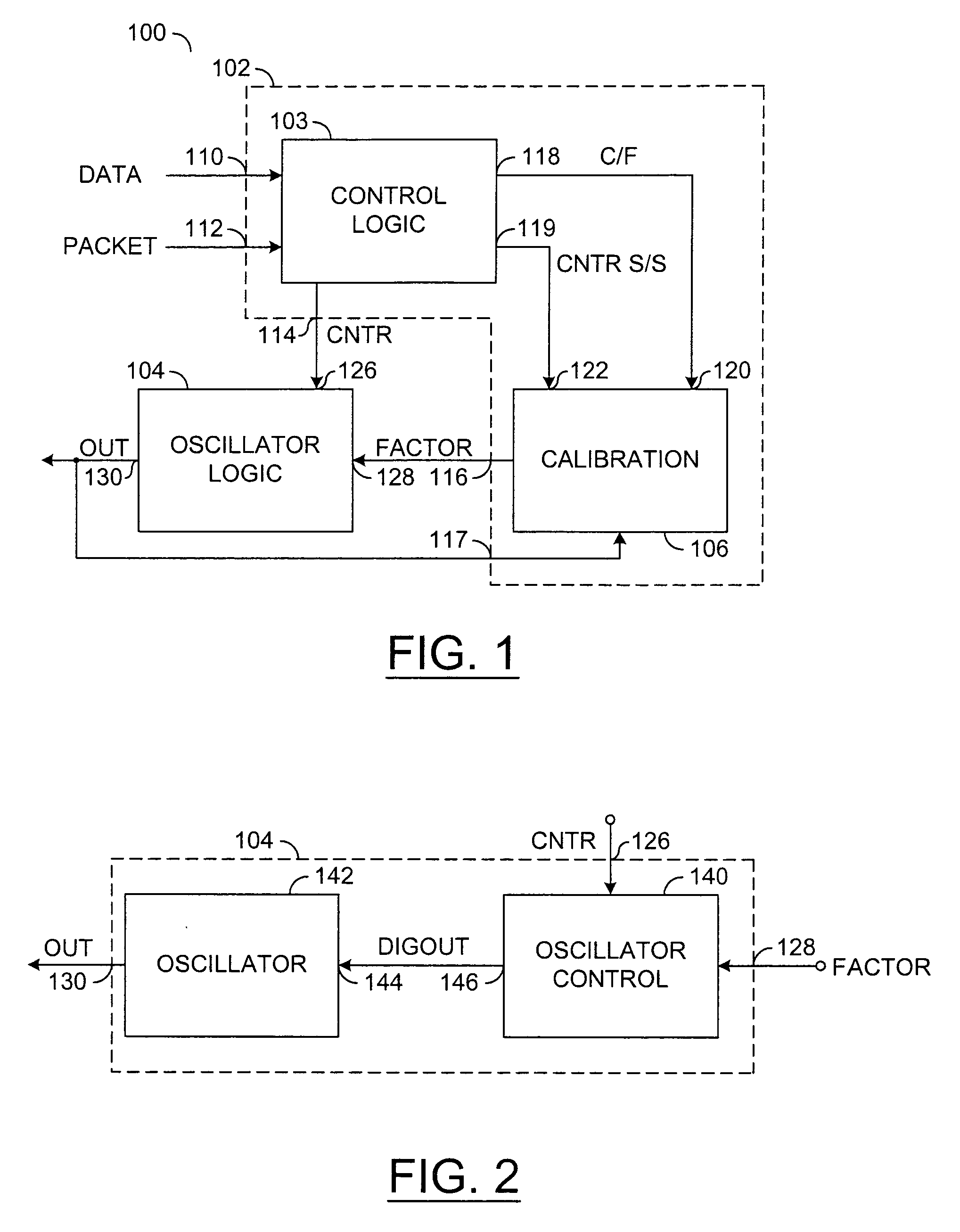
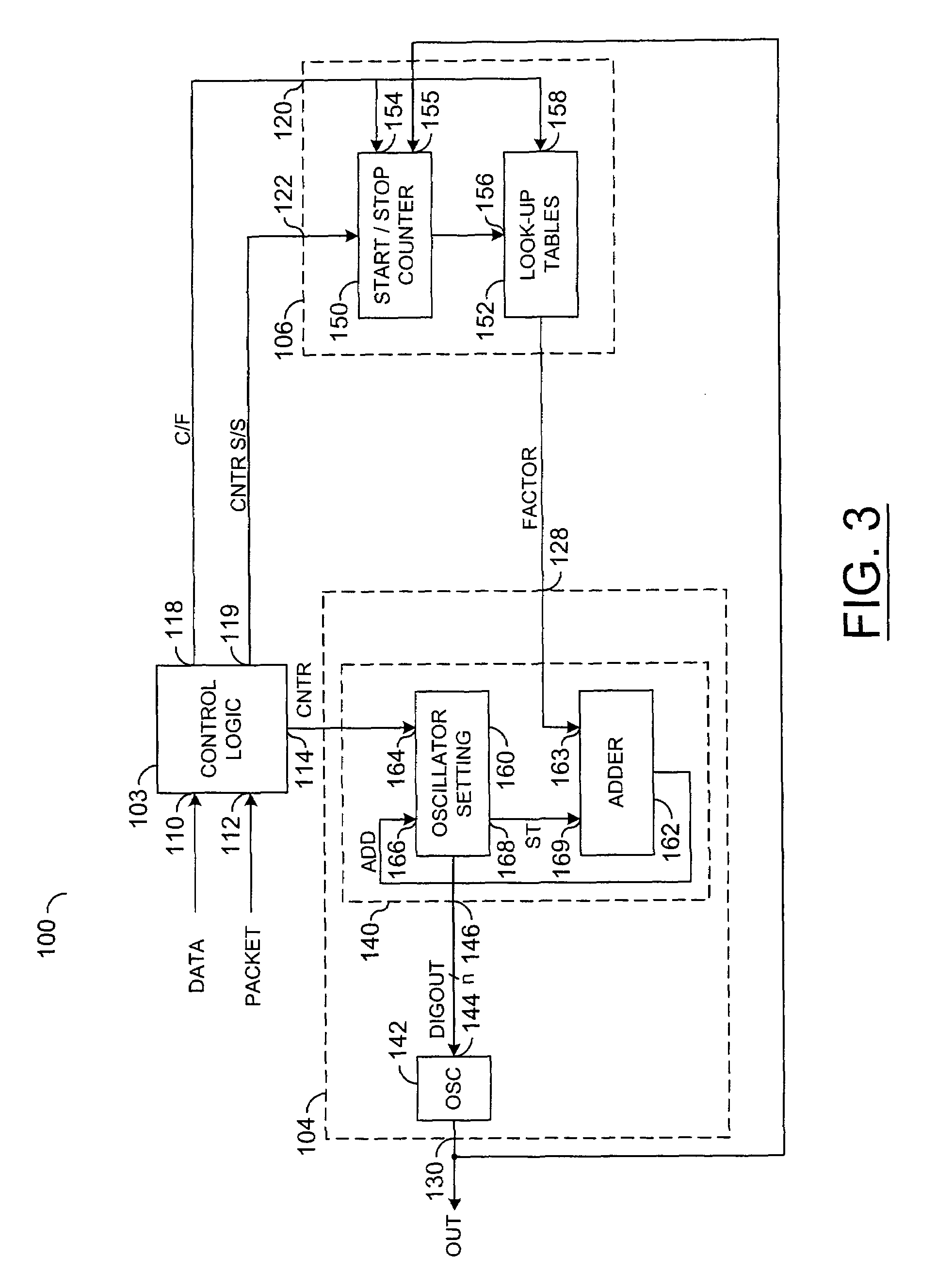
[0013]Referring to FIG. 1, a block diagram of a circuit 100 is shown in accordance with a preferred embodiment of the present invention. The circuit 100 generally comprises a control circuit 102 and an oscillator logic block (or circuit) 104. The control circuit 102 may have an input 110 that may receive an incoming data stream (e.g., DATA), an input 112 that may receive a signal (e.g., PACKET), an output 114 that may present a control signal (e.g., CNTR), an output 116 that may present a control signal (e.g., FACTOR), and an input 117 that may receive a signal (e.g., OUT). The incoming data stream DATA may be a series of data packets that may not necessarily be continuous.

[0014]The control circuit 102 generally comprises a control logic block (or circuit) 103 and a counter block (or circuit) 106. The control logic block 103 may have an output 118 that may present an adjustment signal (e.g., C / F) and an output 119 that may present a control signal (e.g., CNTRS / S). The counter 106 ma...


PUM


Abstract

An apparatus comprising a control circuit and a first circuit. The first circuit may be configured to generate a calibration signal in response to an adjustment signal and a first control signal. The control circuit may be configured to generate (i) the first control signal, (ii) a second control signal and (iii) the adjustment signal in response to a rate of an input signal.

Description

[0001]This is a continuation of U.S. Ser. No. 09 / 966,626 filed Sep. 28, 2001 now U.S. Pat. No. 6,525,616, which is a continuation of U.S. Ser. No. 09 / 511,020 filed Feb. 23, 2000, now U.S. Pat. No. 6,297,705.CROSS REFERENCE TO RELATED APPLICATION[0002]The present application may relate to application Ser. No. 09 / 511,019, filed Feb. 23, 2000, now U.S. Pat. No. 6,407,641, which is hereby incorporated by reference in its entirety.FIELD OF THE INVENTION[0003]The present invention relates to a method and / or architecture for locking a data steam generally and, more particularly, to a method and / or architecture for locking an oscillator to a data stream.BACKGROUND OF THE INVENTION[0004]Conventional approaches for locking a data stream use Phase Lock Loops (PLL) and / or Delay Lock Loops (DLL) to lock or match a clock to an incoming data stream.[0005]Such approaches typically require a very long training sequence and / or a continuous stream of data. Either requirement is incompatible with data ...

Claims


Application Information

Patent Timeline
Patent Type & Authority Patents(United States)
IPC IPC(8): G01R23/00H03L7/00H04J3/06H04L7/00H04L7/033
CPCH03L7/00H04L7/0083H04J3/0632H04L7/033
Inventor WILLIAMS, TIMOTHY J.WICK, JEFFREY D.
Owner MONTEREY RES LLC
Why Eureka
Try Eureka