Integral image readin/writing head, image processor provided with this, image reading head and print head

a technology of image read/write and image processor, which is applied in the direction of inking apparatus, instruments, and semiconductor/solid-state device details, etc., can solve the problems image read/write head h cannot be efficiently manufactured, and the thickness direction of image read/write head becomes bulky, so as to prevent light reflection, reduce noise, and high image reading quality

Inactive Publication Date: 2005-09-20
ROHM CO LTD
View PDF9 Cites 9 Cited by
  • Summary
  • Abstract
  • Description
  • Claims
  • Application Information

AI Technical Summary

Benefits of technology

[0013]With such a structure, by supporting the platen roller by the supporting means, the platen roller can be easily positioned relative to the image read / write head. Further, it is also possible to facilitate the mounting of the platen roller.
[0054]With the printhead having such a structure, it is possible to eliminate or lessen the necessity for separately providing means for detecting the recording paper. Further, it is possible to easily and precisely position the detecting means relative to the respective parts of the printhead. Therefore, it is possible to reduce the cost for manufacturing a printer utilizing the printhead.

Problems solved by technology

Firstly, as described above, the image read / write head H is used in combination with a pair of platen rollers P1 and P2 for a document and a recording paper, respectively. Therefore, it is desired that the image read / write head H has such a structure as to allow easy positioning and mounting of the platen rollers P1 and P2 relative to the image read / write head. However, the prior art image read / write head H does not include such positioning or mounting means, which is inconvenient.
Secondly, the platen rollers P1, P2 are disposed so as to sandwich the image read / write head H, so that the image read / write head H in combination with the platen rollers P1 and P2 becomes bulky in the thickness direction of the image read / write head.
Thirdly, in manufacturing the image read / write head H, after a plurality of light receiving elements 3e are mounted on an obverse surface 40 of a substrate 4, the substrate needs to be turned over for mounting a plurality of heating elements 8 and a plurality of drive IC chips 80 on a reverse surface 41 of the substrate 4. Moreover, wiring patterns with respect to these components also need to be provided on both the obverse and the reverse surfaces 40, 41 of the substrate 4. Therefore, the image read / write head H cannot be efficiently manufactured.
Fourthly, there is a likelihood that the light receiving elements 3e receive inappropriate light which may cause noises. Specifically, with the above-described prior art structure, the light passing through the lenses 5e may be reflected in a scattering manner by the wall surfaces around the light receiving elements 3e, and the scattering light may be received by the light receiving elements 3e. Moreover, light from outside the case 1e may enter the case 1e through a small gap defined between the case 1e and the substrate 4e to be received by the light receiving elements 3e.
Fifthly, with the prior art image read / write head H, it is impossible to determine whether or not the document D is fed onto the transparent cover 19e. Similarly, it is also impossible to determine whether or not the recording paper K is fed on the heating elements 8. Therefore, as indicated by phantom lines in FIG. 15, sensors 99a, 99b for detecting the presence or absence of the document D and the recording paper K, respectively, need to be provided separately from the image read / write head H. With such an arrangement, the sensors 99a, 99b and the image read / write head H need to be individually mounted at respective positions, which makes the manufacturing process of an image processing apparatus troublesome. Further, the image reading operation may be controlled to be interrupted when the document D is advanced by a predetermined distance after the trailing edge of the document D is detected by the sensor 99a. In such a case, it is necessary to precisely set the distance between the sensor 99a and the image reading line Se of the image read / write head H, which is also troublesome.

Method used


Image

  • Integral image readin/writing head, image processor provided with this, image reading head and print head
  • Integral image readin/writing head, image processor provided with this, image reading head and print head
  • Integral image readin/writing head, image processor provided with this, image reading head and print head

Examples


Embodiment Construction

[0071]Preferred embodiments of the present invention will be described below with reference to the accompanying drawings.

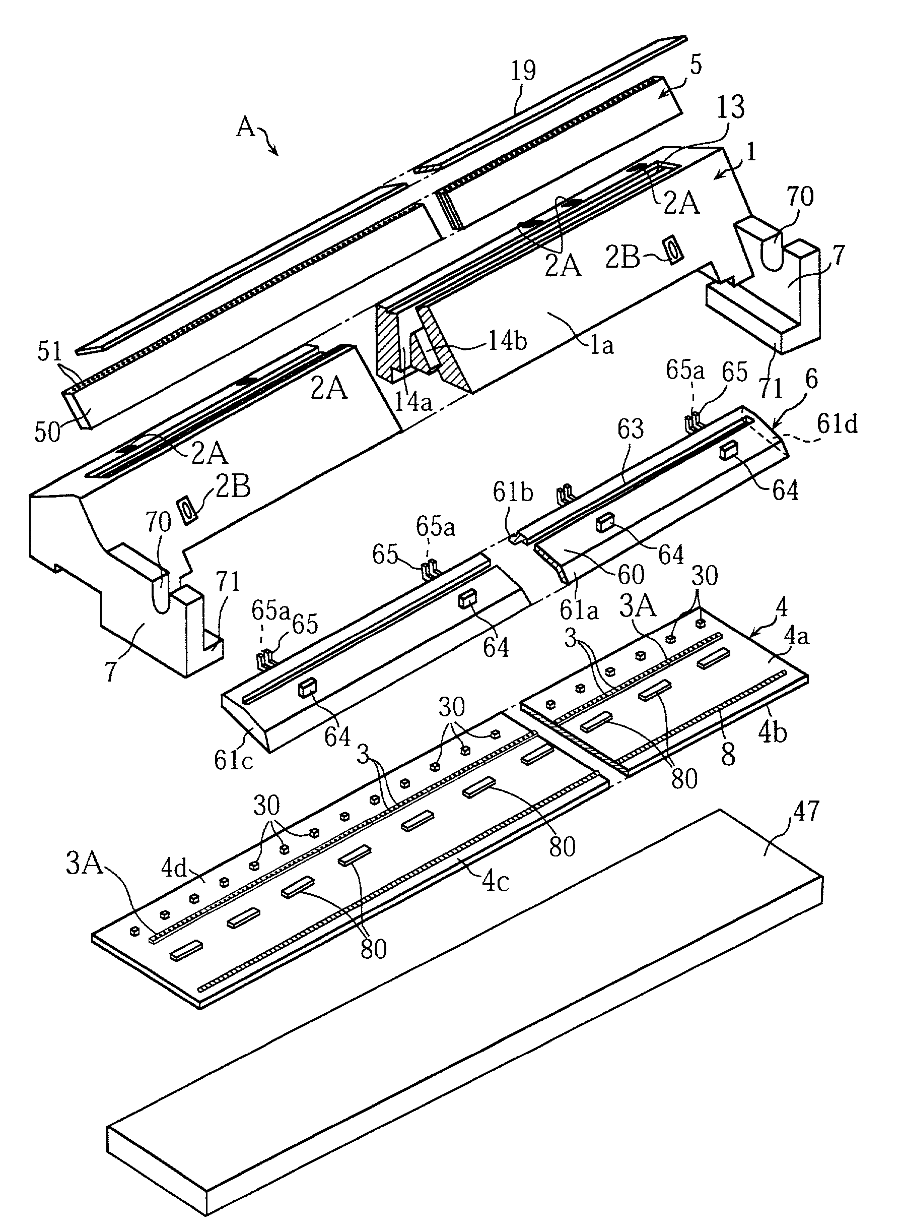
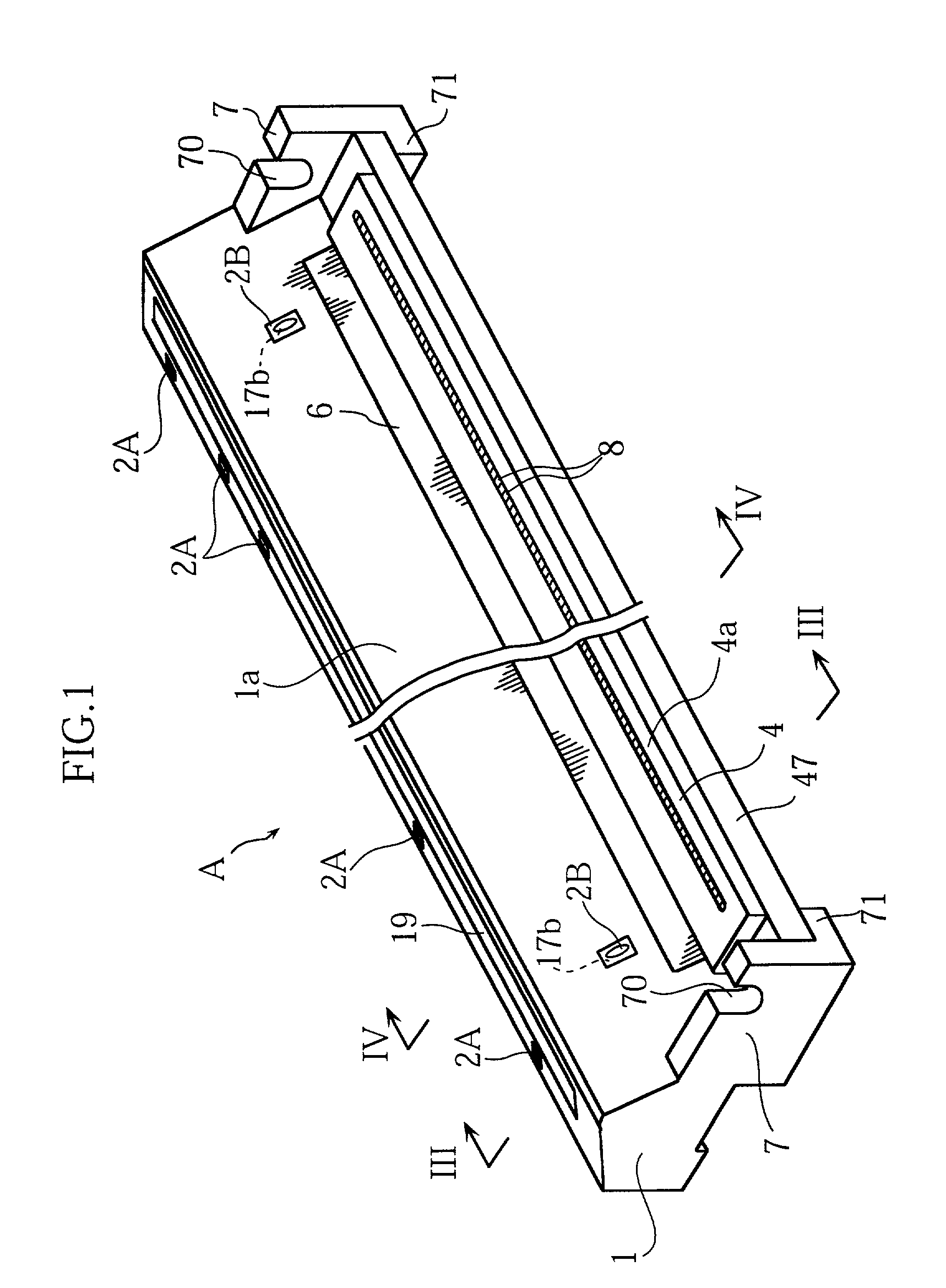
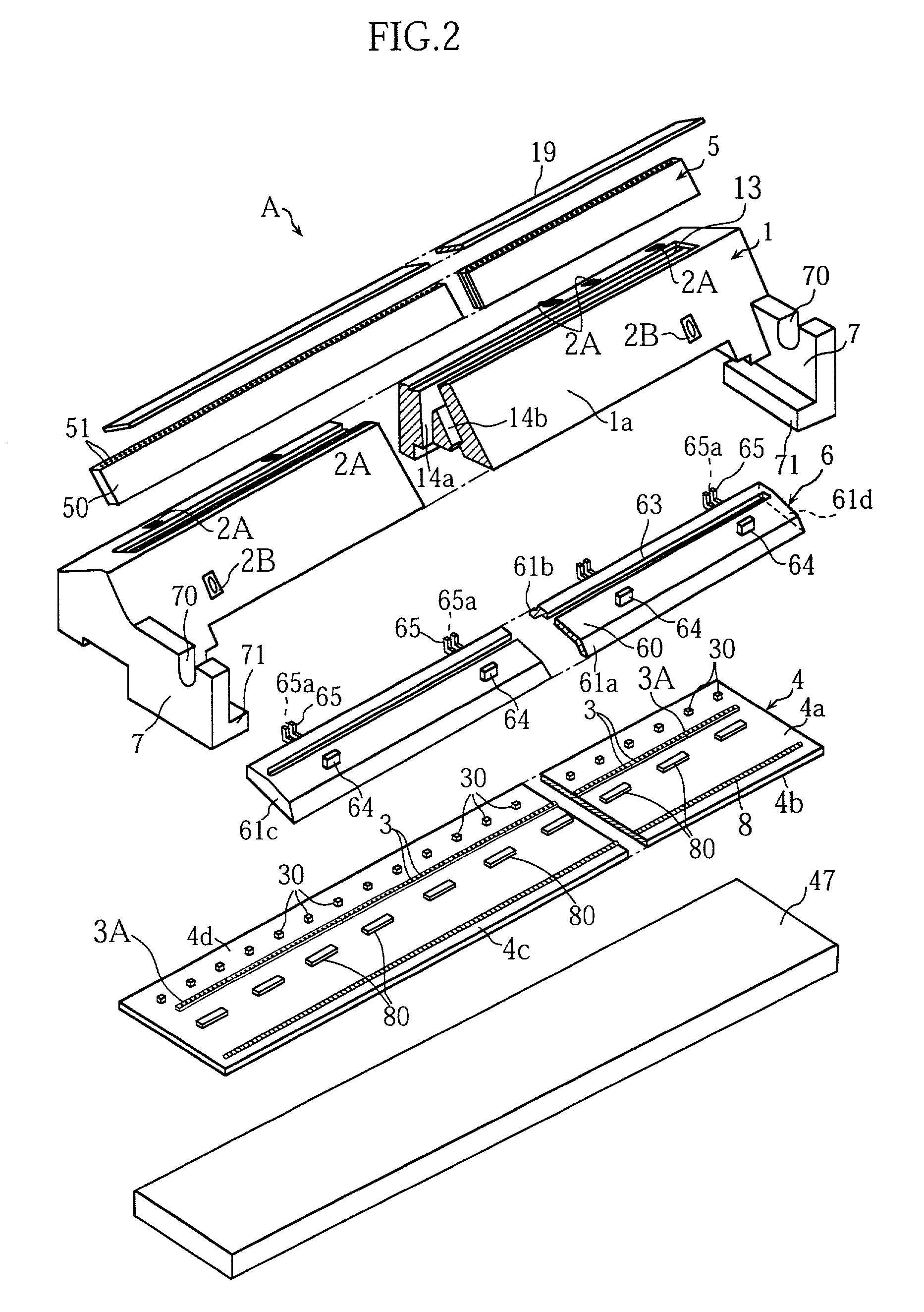
[0072]FIGS. 1 through 5 illustrate an example of image read / write head according to the present invention.

[0073]As clearly shown in FIGS. 1 through 3, the image read / write head A comprises a case 1, a plurality of sensors 2A for detecting a document, a plurality of sensors 2B for detecting a recording paper, a transparent cover 19, a lens array 5, a reflection preventing member 6, a substrate 4, a heat sink plate 47 and other parts which will be described later.

[0074]The substrate 4, which may be made of a ceramic material for example, is in the form of an elongated rectangular plate. The substrate 4 has an obverse surface (upper surface) 4a which is provided with a plurality of light sources 30, a plurality of light receiving elements 3, a plurality of drive IC chips 80 and a plurality of heating elements 8.

[0075]The light sources 30, each of which may comprise a...


PUM


Abstract

An image read / write head (A) includes a support (7) for supporting at least one of paired platen rollers (P1, P2) and a detector (2) for detecting at least one of a document (D) and a recording paper (K). Therefore, an image processing apparatus incorporating the image read / write head (A) can be easily manufactured. The image read / write head (A) further includes a reflection preventing member (6) for collectively surrounding the plurality of light receiving elements (3) and the plurality of drive IC chips (80). Therefore, it is possible to prevent the plurality of light receiving elements from receiving scattering light or disturbing external light.

Description

TECHNICAL FIELD[0001]The present invention relates to an image read / write head having both an image reading function and an image printing function, and an image processing apparatus incorporating such a image read / write head. The present invention also relates to an image read head having an image reading function and a printhead having an image printing function.BACKGROUND ART[0002]Examples of image processing apparatus include a facsimile machine. A facsimile machine needs to have both an image reading function and an image printing function. Further, it is desired that a facsimile machine is so structured to have a size as small as possible.[0003]Therefore, a prior art image read / write head H has the structure as shown in FIG. 15. The image read / write head H includes a case 1e and a transparent cover 19e mounted on an upper portion of the case. The head case 1e accommodates light sources 30e for illuminating an image reading line Se defined on a surface of the transparent cover ...

Claims


Application Information

Patent Timeline
Patent Type & Authority Patents(United States)
IPC IPC(8): B41J2/32H04N1/00H04N1/12H04N1/024H04N1/191H04N1/193
CPCB41J2/32H04N1/00681H04N1/00689H04N1/00782H04N1/024H04N1/02427H04N1/02463H04N1/1215H04N1/193H04N2201/0446
Inventor ONISHI, HIROAKIFUJIMOTO, HISAYOSHI
Owner ROHM CO LTD
Why Eureka
Try Eureka