Apparatus for detecting knocking of internal combustion

a technology for internal combustion and apparatus, applied in the direction of electric control, machines/engines, instruments, etc., can solve the problems of deteriorating an s/n ratio, unable to detect the knocking with precision, and cannot be expected to have the knocking detected with precision

Inactive Publication Date: 2005-09-20
DENSO CORP
View PDF9 Cites 32 Cited by
  • Summary
  • Abstract
  • Description
  • Claims
  • Application Information

AI Technical Summary

Benefits of technology

[0019]By contrast, compared to the second type of filter, the first type of filter is able to provide a filtering characteristic in which each range from its pass band to each stop band has gains attenuated moderately. Hence, even if knocking frequencies shift in some degree due to some factors, such as operation states of the engine and / or aging of the engine, the first type of filter is able respond to the knocking signals, because the filter is wider to respond to such signals thanks to moderate attenuation curves. Accordingly the first type of filter has the capability of sufficiently responding to the knocking signals.
[0020]The combination of the first and second types of filters allows the knocking detection apparatus to have an improved accuracy for detecting the occurrence of the knocking.
[0022]In this way, the first type of filter can be constructed with a lower order. This simplifies circuitry if the filter is an analog filter, while simplifying filtering if the filter is a digital filter.
[0023]In addition, because of the lower filter order, the first type of filter is quicker to response to the peak of a knocking signal. Because of the higher filter order, the second type of filter can be free from being affected by a knocking signal of greater level, thereby detecting a background level (i.e. noise signals). In consequence, an S / N obtained when the peak of a knocking signal can be made larger, being advantageous in detecting the knocking based on the S / N.

Problems solved by technology

However, in the case that, as suggested by the foregoing reference (publication No. 7-293314), the outputs from the plural filters are used to determine whether or not there occurs a knocking phenomenon in a combustion engine, there still exist some problems as follows.
This deteriorates an S / N ratio, whereby the knocking cannot be detected with precision.
In this case, it cannot be expected to have the knocking detected with precision, if the frequencies of the knocking signal (i.e., the knocking frequencies) are shifted due to operation conditions and / or ageing of an engine.

Method used


Image

  • Apparatus for detecting knocking of internal combustion
  • Apparatus for detecting knocking of internal combustion
  • Apparatus for detecting knocking of internal combustion

Examples


first embodiment

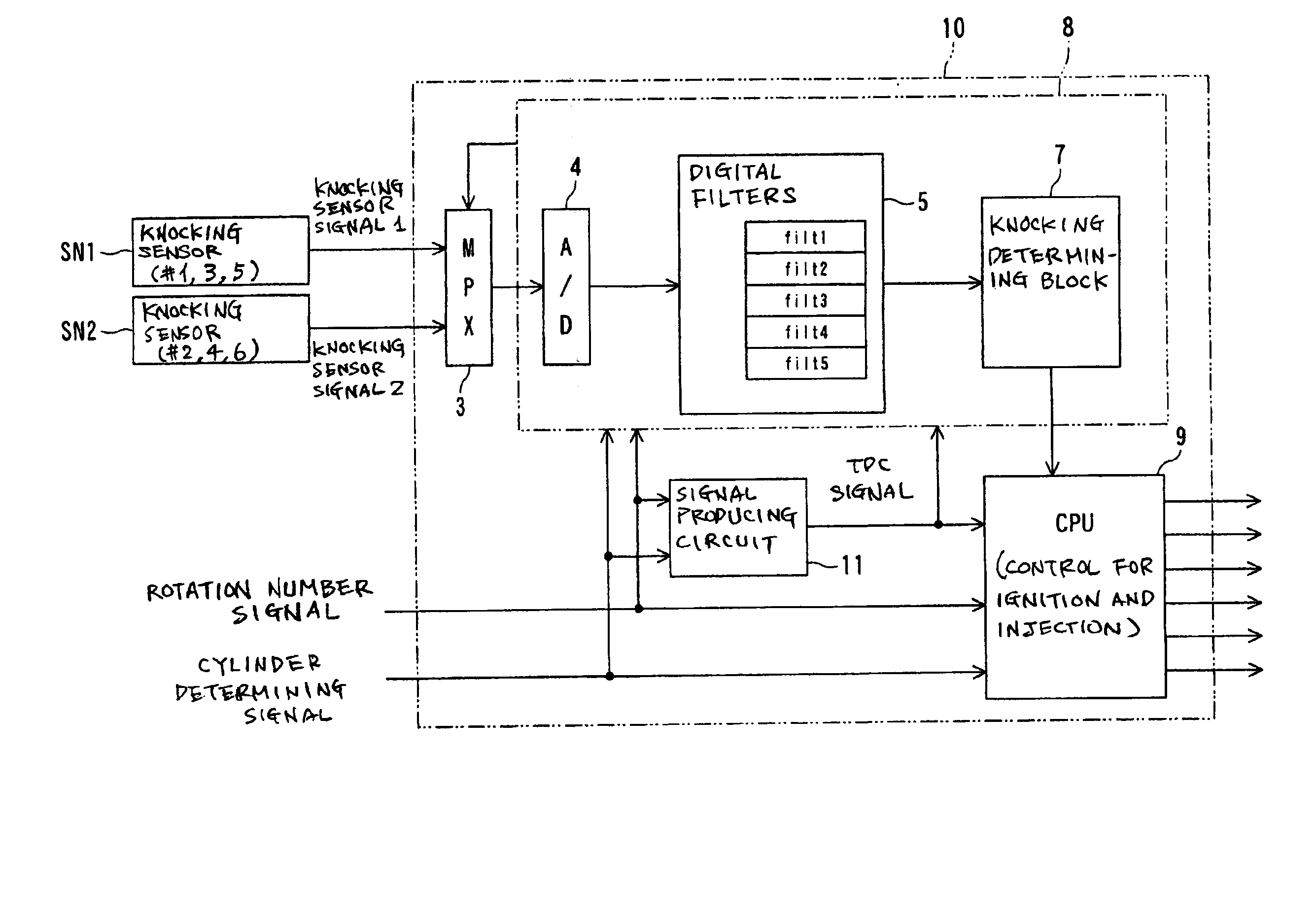
[0043]Referring to FIGS. 1 to 10, a first embodiment of the present invention will now be described. In this embodiment, an engine control apparatus 10 for a gasoline engine with 6 cylinders (i.e., an internal combustion) is exemplified, in which the knocking detection apparatus according to the present invention is reduced into practice.

[0044]As shown in FIG. 3, the engine control apparatus 10 according to the first embodiment is configured to receive two knocking sensors SN1 and SN2. One knocking sensor SN1 is attached to the engine to detect knocking conditions of three cylinders among all the six cylinders. In this embodiment, such cylinders assigned to the knocking sensor SN1 are the first, third and fifth cylinders #1, #3 and #5. This sensor SN1 outputs an analog-quantity signal indicative of knocking states of those cylinders (hereinafter, referred to as a knocking signal 1). On the other hand, the other knocking sensor SN2 is also attached to the engine to detect knocking co...

first modification

[0094]A first modification relates to the sharper inclinations given to the filters filt4 and filt5. By way of example, to make the filters filt4 and filt5 steeper in the inclinations of the filtering characteristics at their cut-off frequencies than the remaining filters filt1 to filt3, filtering factors (amounts “a” and “b” in FIG. 5) may be adjusted to raise the Q values of the filters filt4 and filt5 over that of the filters filt3 and filt4, with the orders of the filters filt1 to filt5 maintained at the same value (for example, the fourth-order).

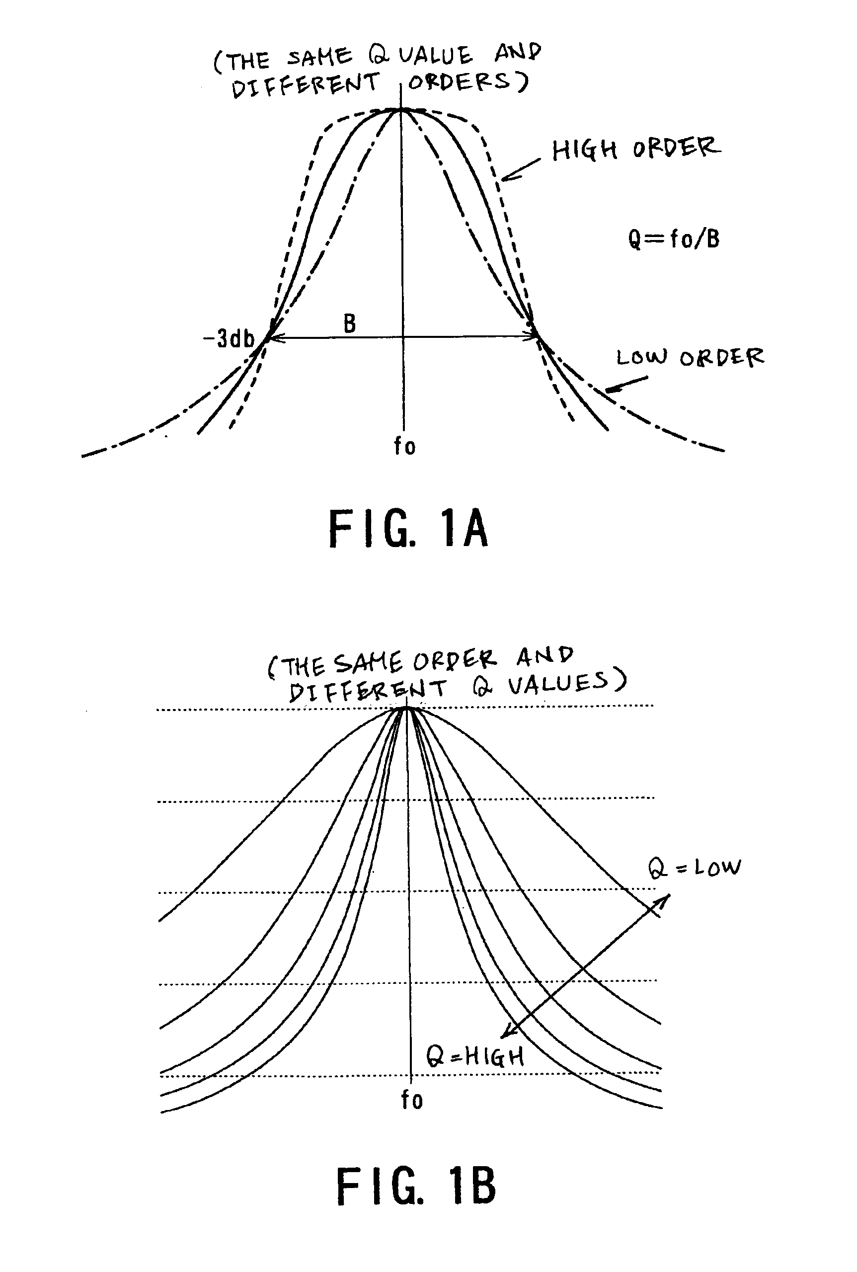
[0095]There can be provided a practical example in which the filters filt4 and filt5 are set to have a Q value of 25 dB, while the filters filt1 to filt3 are set to have a Q value of 10 dB or 6 dB. This construction is based on the fact that, as shown in FIG. 1B, the higher the Q value, the sharper the filtering characteristic at the cut-off frequency, provided that the filter orders are the same. It is not necessarily limited, however,...

second modification

[0097]A second modification concerns with types of filters that can be applied to the present invention.

[0098]FIR filters can be used as the filters filt1 to filt5, instead of the IIR filters, in the foregoing first embodiment and the foregoing first modification. The configuration of a typical FIR (finite impulse response) filter is exemplified in FIG. 10, though it is well known.


PUM

PropertyMeasurementUnit
center frequenciesaaaaaaaaaa

Abstract

An apparatus is provided for detecting an occurrence of knocking of an engine from a signal sensed by a knocking sensor for the engine. The apparatus comprises plural filters extracting, from the signal, plural signal components whose frequency bands mutually differ and a unit determining whether or not there is the occurrence of knocking, based on results outputted from the plural filters. The plural filters include first and second types of filters. The first type of filter has a pass band set to a specific frequency band including a specific frequency of the signal. This specific frequency indicates the occurrence of knocking. The second type of filter has a pass band set to another specific frequency band. An inclination of a filtering characteristic of the second type of filter at a cut-off frequency thereof is steeper than that the first type of filter.

Description

BACKGROUND OF THE INVENTION[0001]1. Technical Field[0002]The present invention relates to an apparatus for detecting knocking occurring in an internal combustion.[0003]2. Related Art[0004]For driving an internal combustion, it is usually required to have an apparatus for detecting knocking occurring in the internal combustion. Conventional techniques for detecting the occurrence of knocking have already been proposed by various references.[0005]One example is disclosed by a Japanese Patent Laid-open (unexamined) publication No. 7-293314 (refer to pages 2-3 and FIG. 5 thereof).[0006]This reference discloses determination as to whether or not there occurs a knocking of an internal combustion. Practically, a knocking sensor is used to detect a signal indicative of a knocking of an internal combustion. This signal from the knocking sensor is subjected to A / D conversion at specified sampling intervals. The A / D-converted data, which are outputted sequentially in time, is sent to a plurali...

Claims


Application Information

Patent Timeline
Patent Type & Authority Patents(United States)
IPC IPC(8): G01L23/00G01L23/22G01H17/00F02D45/00G01M15/00
CPCG01L23/225
Inventor HONDA, TAKAYOSHI
Owner DENSO CORP
Why Eureka
Try Eureka