Simplified tiling pattern method

a technology of integrated circuits and tiling patterns, which is applied in the direction of cad circuit design, instrumentation, and semiconductor/solid-state device details, etc., can solve the problems of inability to make consistent assumptions about the impact of electrical properties of fill tile patterns on electrical analysis, fill tiles add complexity to the electrical analysis of the circuit, and the fill tile environment is non-uniform relative to the wiring, etc., to achieve uniform density and electrical characteristics

Inactive Publication Date: 2005-09-20
IBM CORP
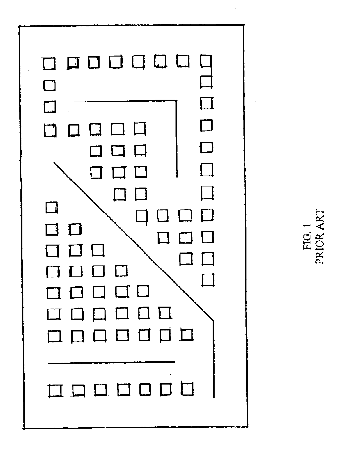
View PDF10 Cites 20 Cited by
  • Summary
  • Abstract
  • Description
  • Claims
  • Application Information

AI Technical Summary

Benefits of technology

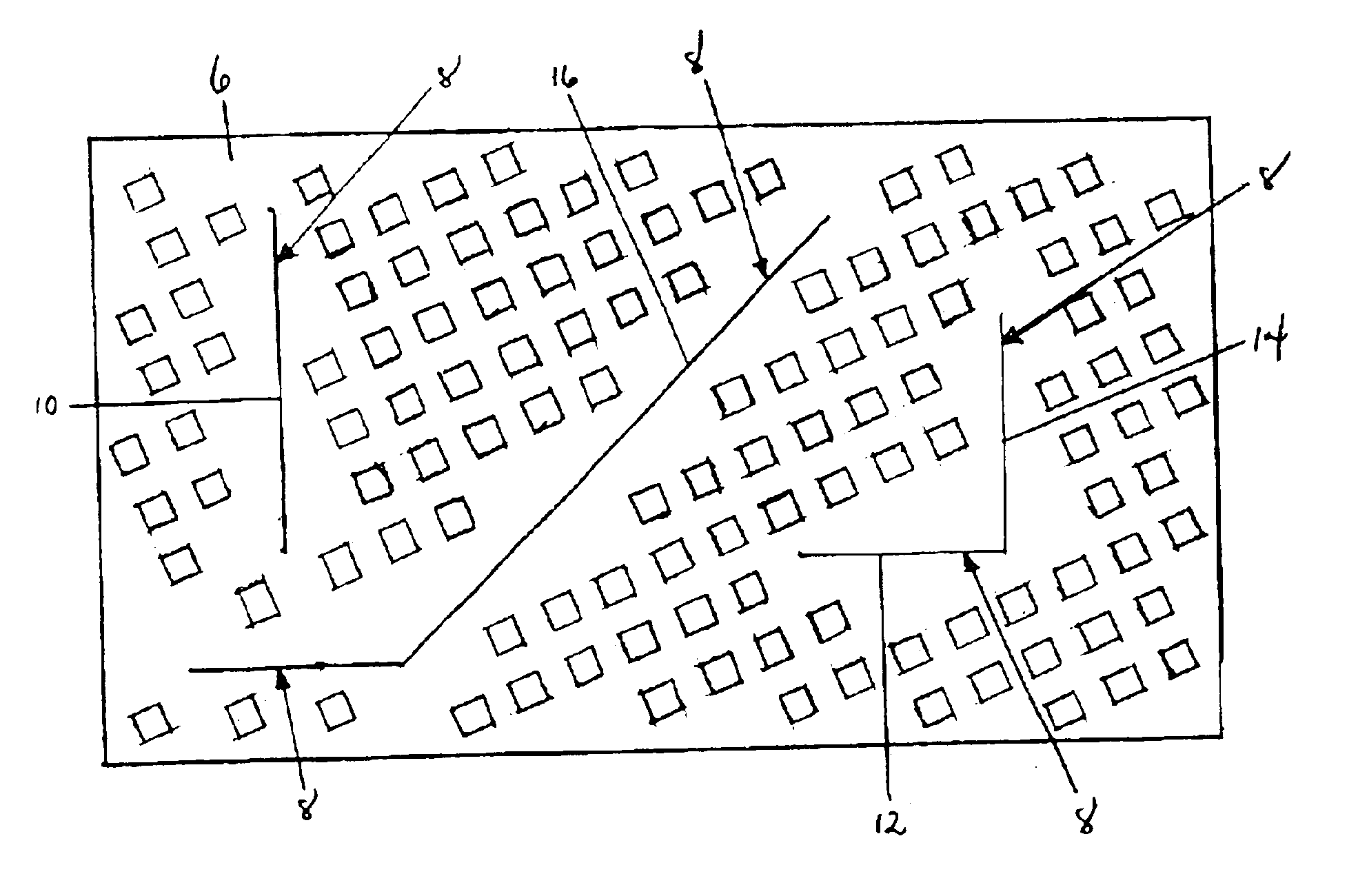
[0008]The invention relates to fill tiling of wiring patterns. Typical non-orthogonal wiring patterns involve the use of wires constrained to 45 degrees relative to orthogonal wires. This constraint simplifies the problem of providing a tiling pattern which results in uniform electrical characteristics for all wires. The invention provides a method for providing a substantially uniform density and electrical characteristics between parts of an IC that are either orthogonal or angled at 45 degrees relative to one another. The invention does so by providing an integrated circuit design or integrated circuit including at least one layer having a first electrical structure angled at 45 degrees relative to a second electrical structure, wherein the fill tiles in the tiling pattern in combination with the first and second electrical structures provide a substantially uniform density and electrical characteristics across a respective layer of the IC.

Problems solved by technology

One challenge in providing uniform density of wiring within a plane is addressing the effect of fill tiling patterns on the electrical properties, i.e., fill tiles acting as fringe capacitance, on an adjacent wire.
In particular, fill tiles add complexity to the electrical analysis of the circuit because each shape represents a floating conductor coupled by capacitors to the wire.
Unfortunately, the provision of mixed orthogonal and non-orthogonal wiring with orthogonal fill tile patterns makes the fill tile environment non-uniform relative to the wiring.
Accordingly, consistent assumptions about the impact on electrical properties of the fill tile patterns are no longer possible.

Method used


Image

  • Simplified tiling pattern method
  • Simplified tiling pattern method
  • Simplified tiling pattern method

Examples


Embodiment Construction

[0015]Best Mode(s) for Carrying Out the Invention

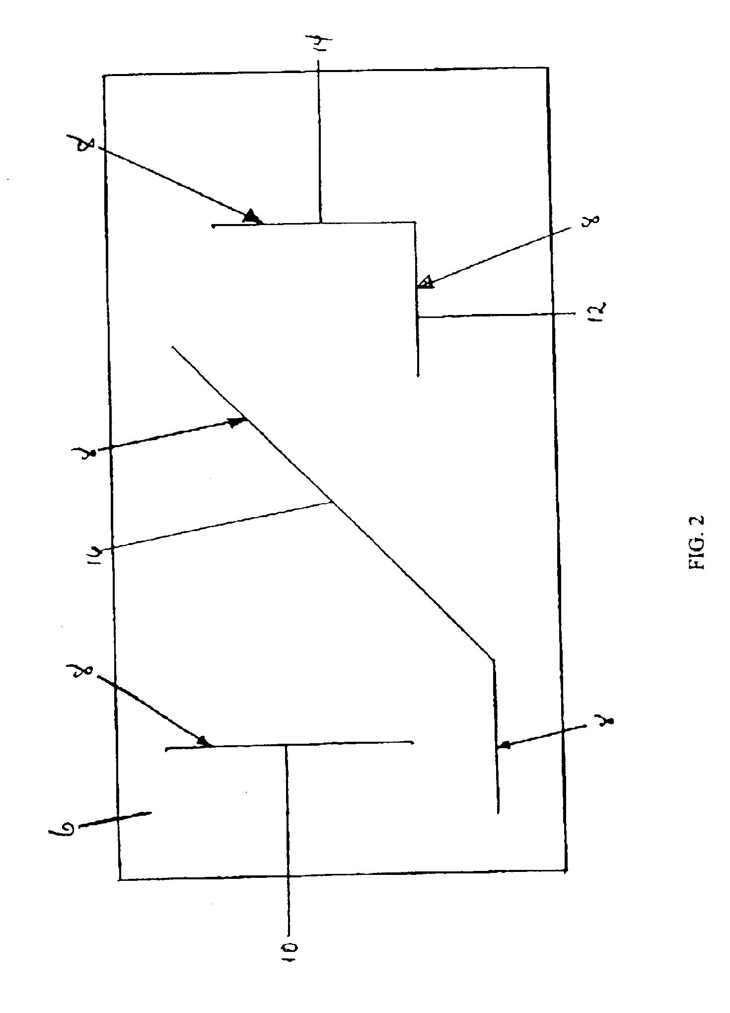
[0016]With reference to the accompanying drawings, FIG. 2 shows a layer of an integrated circuit (IC) 6 including, inter alia, a number of electrically impressionable parts 8. By “impressionable” is meant that the parts are susceptible to environmental influences that can alter their electrical properties. Hereinafter, electrically impressionable parts 8 will be described as wire segments 10, 12, 14, 16. It should be recognized, however, that parts 8 may be any structure of IC 6 that is electrically impressionable such as resistors, wells, power bus segments, shielding structures, ground planes, wave guides, etc. In one embodiment, wire segments 10, 12, 14 may be considered orthogonal because of their relation to each other and / or other structure of IC 6 (e.g., a “top” surface 18), and segment 16 may be considered non-orthogonal because of its 45 degree angle to segments 10, 12, 14 or other structure of IC 6. It should be recognized t...


PUM


Abstract

The invention provides a design and an integrated circuit having a substantially uniform density and electrical characteristics between parts of the IC that are angled at 45 degrees relative to one another. In particular, the invention provides fill tiling patterns oriented substantially uniformly to electrical structures of either orthogonal or 45 degree angle orientation.

Description

BACKGROUND OF THE INVENTION[0001]1. Technical Field[0002]The present invention relates generally to fill tiling patterns for an integrated circuit.[0003]2. Background Art[0004]Current integrated circuit (IC) manufacturing techniques benefit from a uniform density of wiring or conductors within a layer. For example, uniform density is required to prevent different amounts of wear across a plane during chemical mechanical polishing. To provide uniform density, various techniques for filling of empty spaces have been developed. See, for example, U. S. Pat. Nos. 5,278,105 (Eden et al.), 5,341,310 (Gould et al.) or 5,923,563 (Lavin et al.).[0005]One challenge in providing uniform density of wiring within a plane is addressing the effect of fill tiling patterns on the electrical properties, i.e., fill tiles acting as fringe capacitance, on an adjacent wire. In particular, fill tiles add complexity to the electrical analysis of the circuit because each shape represents a floating conductor...

Claims


Application Information

Patent Timeline
Patent Type & Authority Patents(United States)
IPC IPC(8): G06F17/50
CPCG06F17/5068H01L23/528H01L2924/0002H01L2924/00G06F30/39
Inventor ALLEN, ROBERT J.COHN, JOHN M.HABITZ, PETER A.LEIPOLD, WILLIAM C.WEMPLE, IVAN L.ZUCHOWSKI, PAUL S.
Owner IBM CORP
Why Eureka
Try Eureka