Corrugated tube-mounting structure

a corrugated tube and tube-mounting technology, which is applied in the direction of insulated conductors, power cables, cables, etc., can solve the problems of affecting the inserting operation, requiring a lot of time and labor, and the insulating sheath of the wire harness is damaged, so as to achieve the effect of convenient bending

Active Publication Date: 2005-09-27
THE UNITED STATES OF AMERICA AS REPRESENTED BY THE SECRETARY OF THE NAVY +1
View PDF7 Cites 18 Cited by
  • Summary
  • Abstract
  • Description
  • Claims
  • Application Information

AI Technical Summary

Benefits of technology

[0017]It is therefore an object of this invention to provide a corrugated tube-mounting structure in which a corrugated tube of the overlapping type can be easily bent along an installation path.

Problems solved by technology

However, when such a corrugated tube is bent along an installation path, the slit is partially opened in the vicinity of a central portion of the bent portion, and the inserted wire harness or the like projects outwardly through the opened portion of the slit, thus adversely affecting the inserting operation, and besides there is a probability that the wire harness is caught by the opposed side edges of the slit, so that an insulating sheath of the wire harness is damaged.
However, there has been encountered a problem that this taping operation requires much time and labor.
Therefore, when bending the corrugated tube 1 along the installation path, the corrugated tube 1 itself can not be easily bent, and therefore there has been encountered a problem that the installation operation can be adversely affected.

Method used


Image

  • Corrugated tube-mounting structure
  • Corrugated tube-mounting structure
  • Corrugated tube-mounting structure

Examples


first embodiment

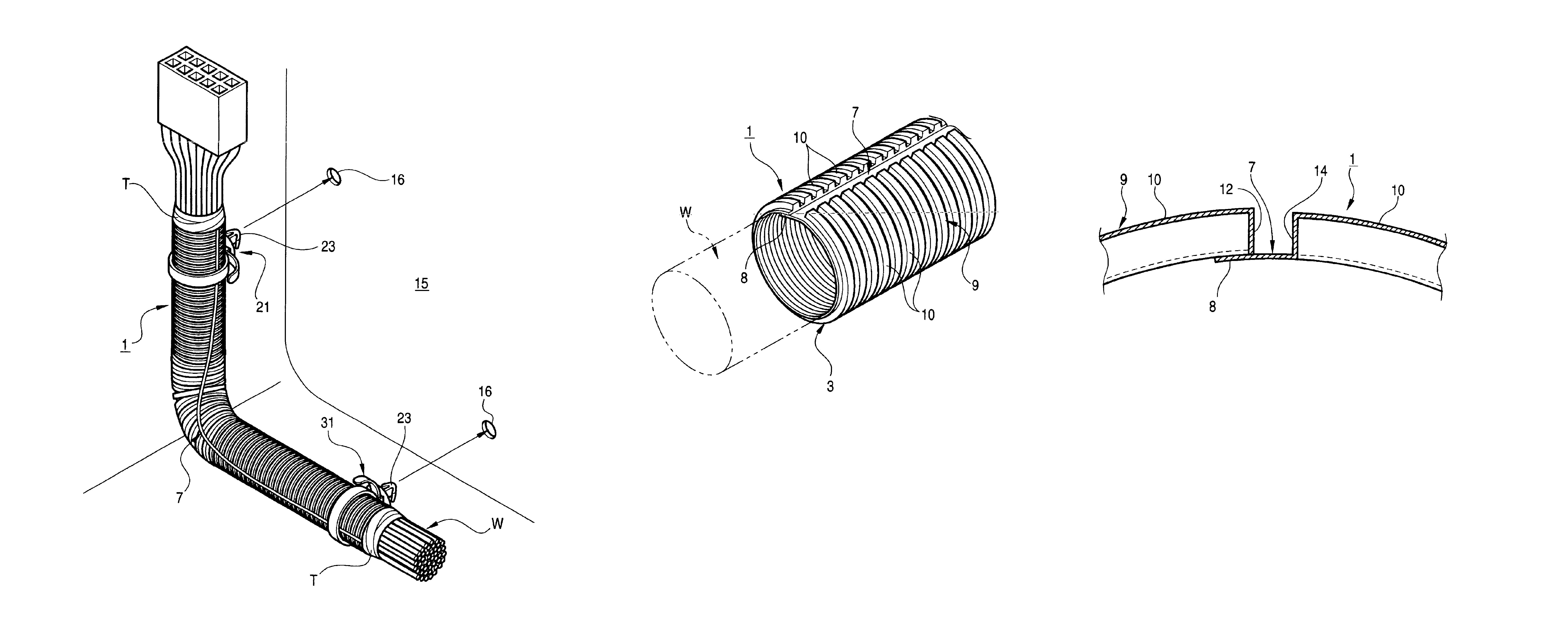
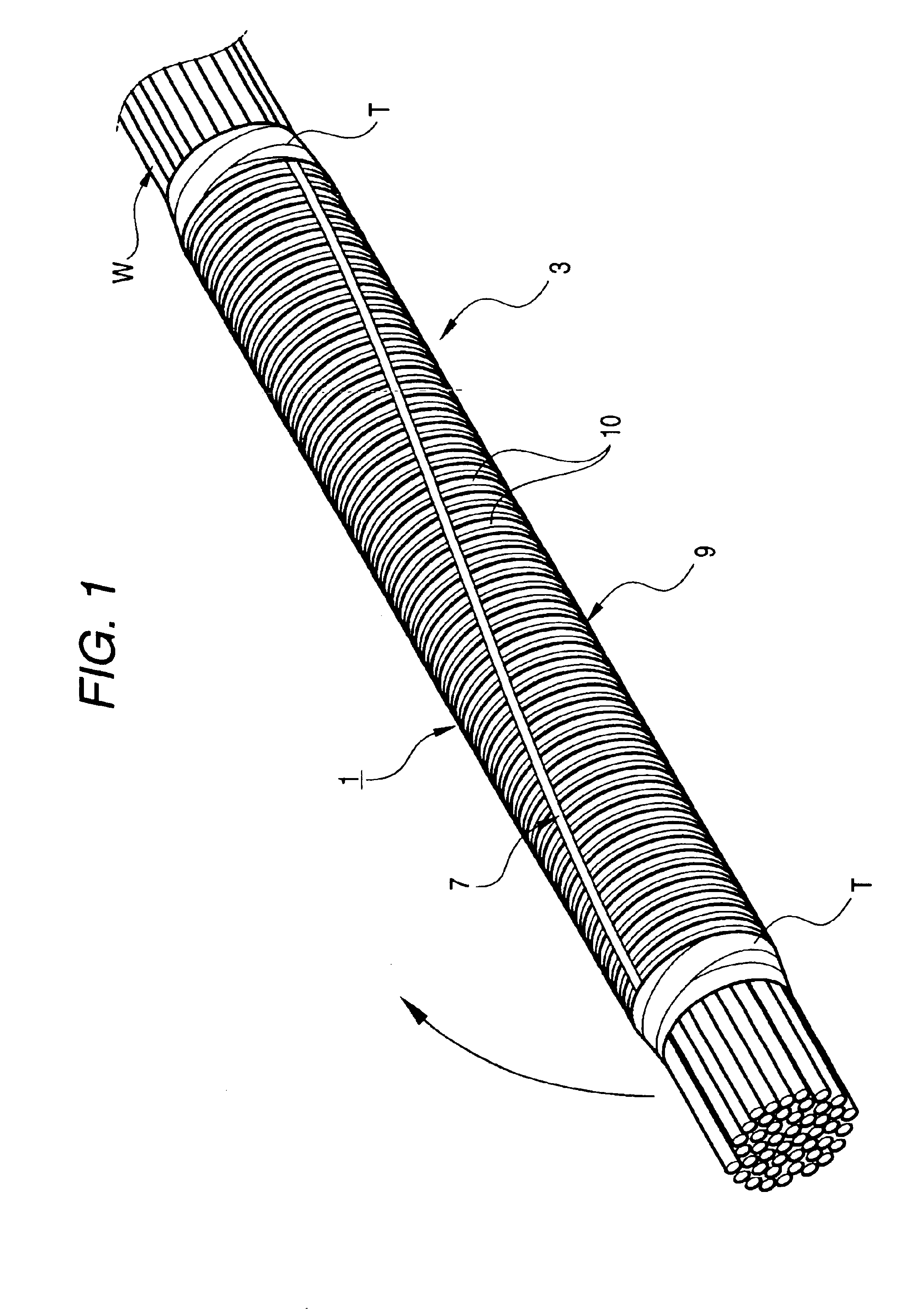
[0055]A corrugated tube 1, used in a mounting structure is fixed to a predetermined portion of a wire harness W by adhesive tapes T or the like wound respectively on opposite end portions thereof, as shown in FIG. 1. At this time, a tubular body 3 is beforehand fixed to the wire harness W, passing therethrough, in such a manner that this tubular body 3 is twisted about an axis thereof relative to the wire harness W.

[0056]Namely, the tubular body 3 is twisted about the axis thereof, so that a lap portion 8 extends spirally along an outer peripheral face of the tubular body 3. In this embodiment, although the tubular body 3 is twisted about the axis thereof through an angle of about 90 degrees, this twisting angle can be suitably changed in accordance with the overall length of the tubular body 3 and so on.

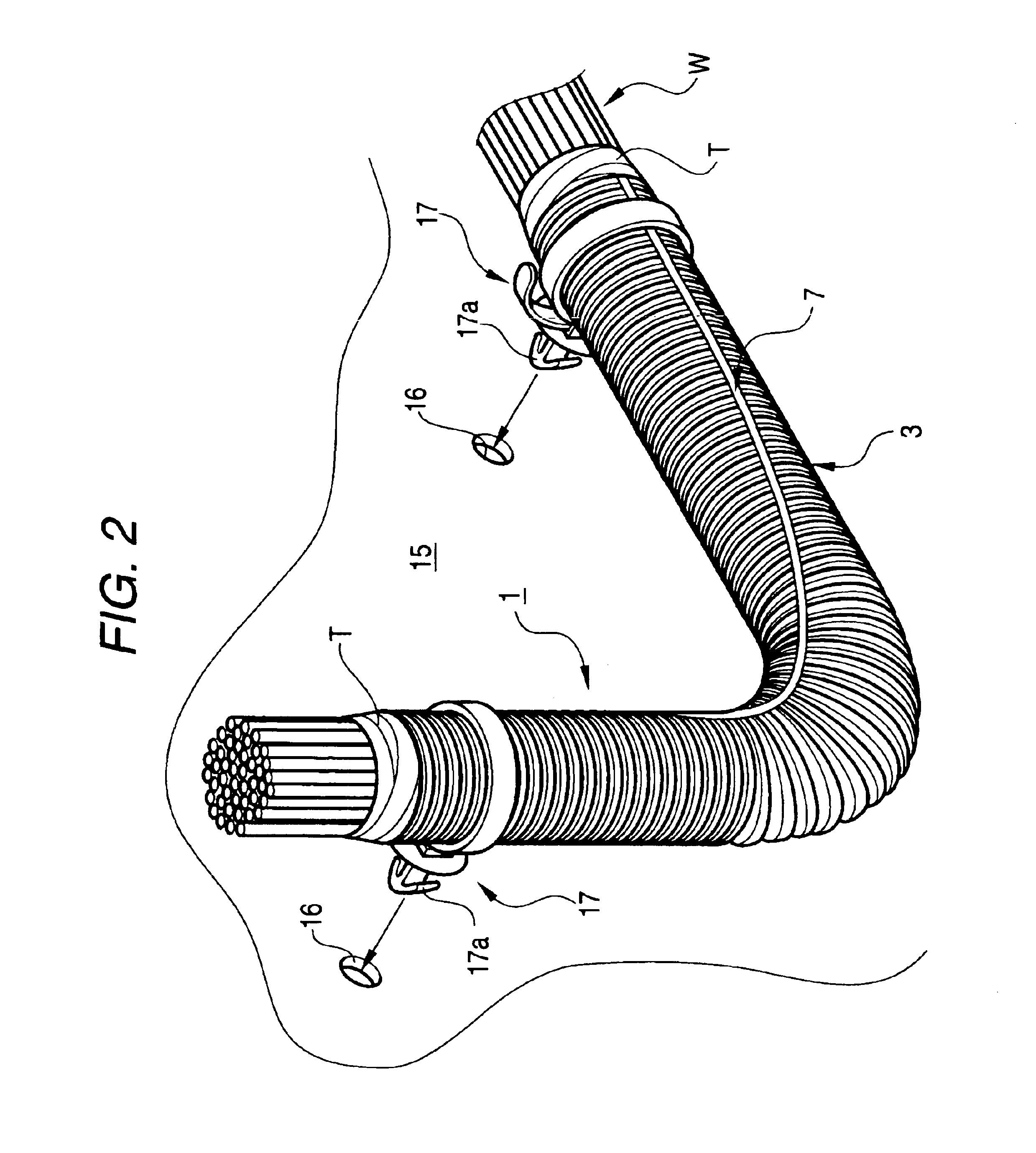
[0057]As shown in FIG. 2, the corrugated tube 1, together with the wire harness W, is fixed to a vehicle body panel 15 of a vehicle, for example, by inserting clip portions 17a of ...

second embodiment

[0060]A corrugated tube 1, used in a mounting structure is fixed to a predetermined portion of a wire harness W by adhesive tapes T or the like wound respectively on opposite end portions thereof, as shown in FIG. 3.

[0061]At this time, a tubular body 3 need only to be fixed to the wire harness W, passing therethrough, in such a manner that the opposite end portions of this tubular body 3 are fixed straight to the wire harness W as is the case with the tubular body 3 of FIG. 11, and therefore the operation for fixing the tubular body 3 to the wire harness W is easy.

[0062]Then, a pair of band clips (clamp members) 21 and 31 are fastened respectively on those portions of the outer peripheral face of the tubular body 3 disposed near respectively to the opposite ends of this tubular body 3.

[0063]As shown in FIG. 4, the band clip 21 is integrally molded of an insulative resin material, and includes a winding bland 24 for being wound on the outer peripheral face of the tubular body 3, a b...


PUM

PropertyMeasurementUnit
angleaaaaaaaaaa
flexibilityaaaaaaaaaa
timeaaaaaaaaaa

Abstract

A corrugated tube includes a tubular body, formed with a slit extending in an axial direction of the tubular body; a plurality of ridge portions, formed on an outer periphery of the tubular body and arranged side by side in the axial direction; and a lap portion, protruded from one of opposed end portions of the tubular body which are separated by the slit and extended toward an inner face of the other opposed end portion of the tubular body. A plurality of fixation members are provided on the outer periphery of the tubular body to fix the corrugated tube onto the panel body in a state that the tubular body is so twisted that the slit is spirally extended.

Description

BACKGROUND OF THE INVENTION[0001]This invention relates to a structure of mounting a corrugated tube for fitting on a wire harness or the like, and more particularly to a structure of mounting a corrugated tube of the overlapping type in which a lap portion, formed in a projected manner at one of opposed side edges of a slit formed in the corrugated tube in an axial direction thereof, is laid on an inner face of the other side edge portion.[0002]Generally, in a corrugated tube used for bundling and protecting electric wires for an electronic equipment, a wire harness for a vehicle or others, spiral or annular ridge portions are formed continuously on an outer peripheral face of a resin tube to form a bellows-like construction, thereby imparting flexibility to the corrugated tube.[0003]In order that a wire harness or the like can be easily inserted into and removed from the corrugated tube for protecting the wire harness, a slit is formed in the corrugated tube, and extends in the ax...

Claims


Application Information

Patent Timeline
Patent Type & Authority Patents(United States)
IPC IPC(8): H02G3/04F16L3/137F16L57/00H02G3/30H02G3/38
CPCH02G3/0468Y10S285/903Y10T29/49194Y10T29/49201Y10T29/49947Y10T29/49195Y10T29/5187
Inventor TADOKORO, SHINICHI
Owner THE UNITED STATES OF AMERICA AS REPRESENTED BY THE SECRETARY OF THE NAVY
Why Eureka
Try Eureka