Methods and apparatus for flade engine nozzle

a flade engine and nozzle technology, applied in the direction of machines/engines, jet flaps, transportation and packaging, etc., can solve the problems of increasing the cost, weight and maintenance of such engines, not operating as efficiently as variable exhaust nozzle systems, and correspondingly reducing engine operating efficiency

Inactive Publication Date: 2005-09-27
GENERAL ELECTRIC CO
View PDF13 Cites 16 Cited by
  • Summary
  • Abstract
  • Description
  • Claims
  • Application Information

AI Technical Summary

Problems solved by technology

The geometry of fixed nozzle systems are not kinematically changed or variable and as such may not operate as efficiently as variable exhaust nozzle systems.
However, the use of an overlapping flap and seal structure in the nozzle design may result in numerous leakage paths which may cause a corresponding decrease in engine operating efficiency.
Additionally, the relatively large quantity of parts used to fabricate the nozzle may increase the cost, weight, and maintenance of such engines.

Method used


Image

  • Methods and apparatus for flade engine nozzle
  • Methods and apparatus for flade engine nozzle
  • Methods and apparatus for flade engine nozzle

Examples


Embodiment Construction

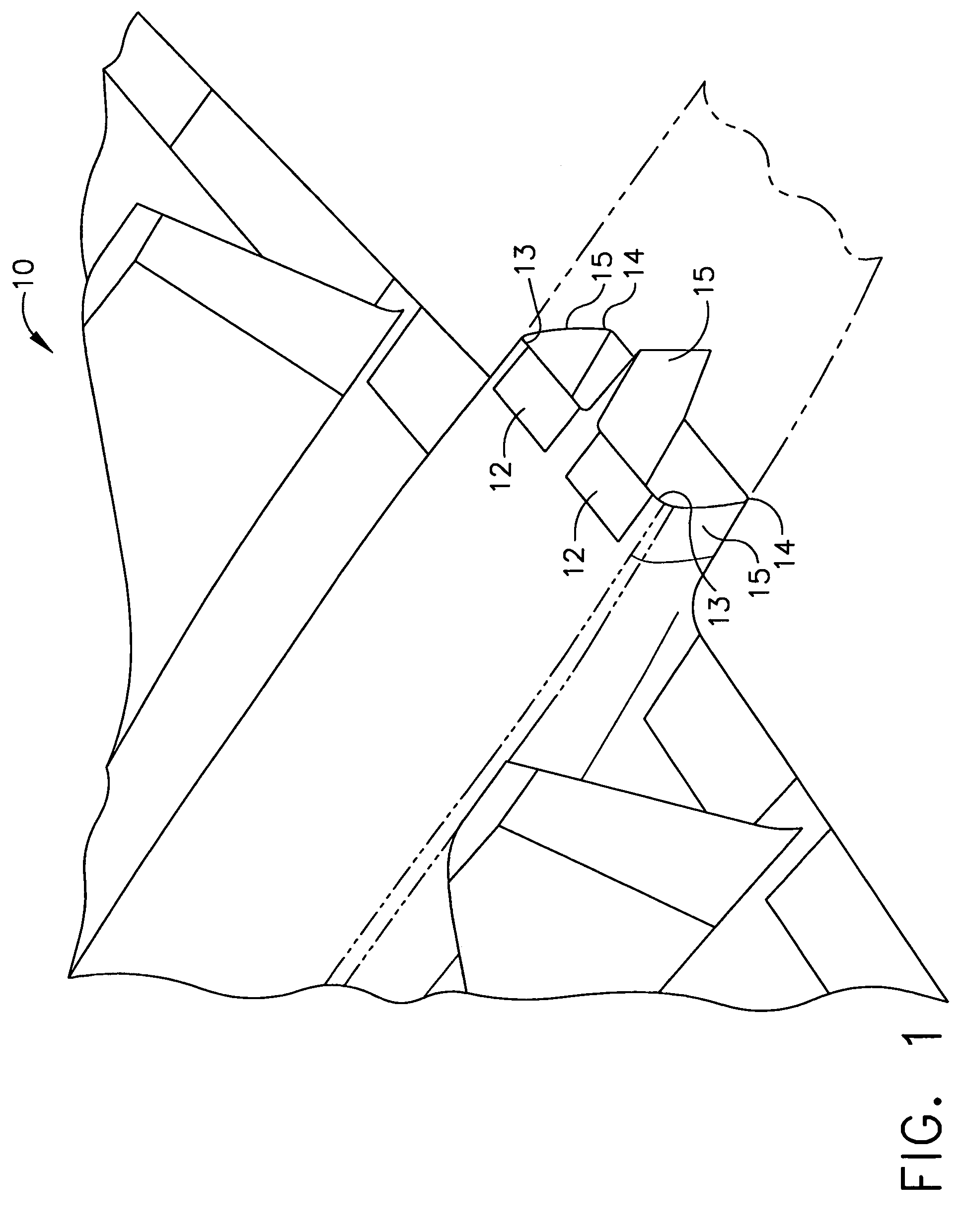
[0017]FIG. 1 is a schematic illustration of a portion of a jet aircraft 10 including a plurality of engines (not shown) and a plurality of nozzle assemblies 12. Each nozzle assembly 12 includes an upper portion 13, a lower portion 14, and a plurality of sidewalls 15 that are coupled together. In the exemplary embodiment, each nozzle assembly 12 has a substantially rectangular cross-sectional profile.

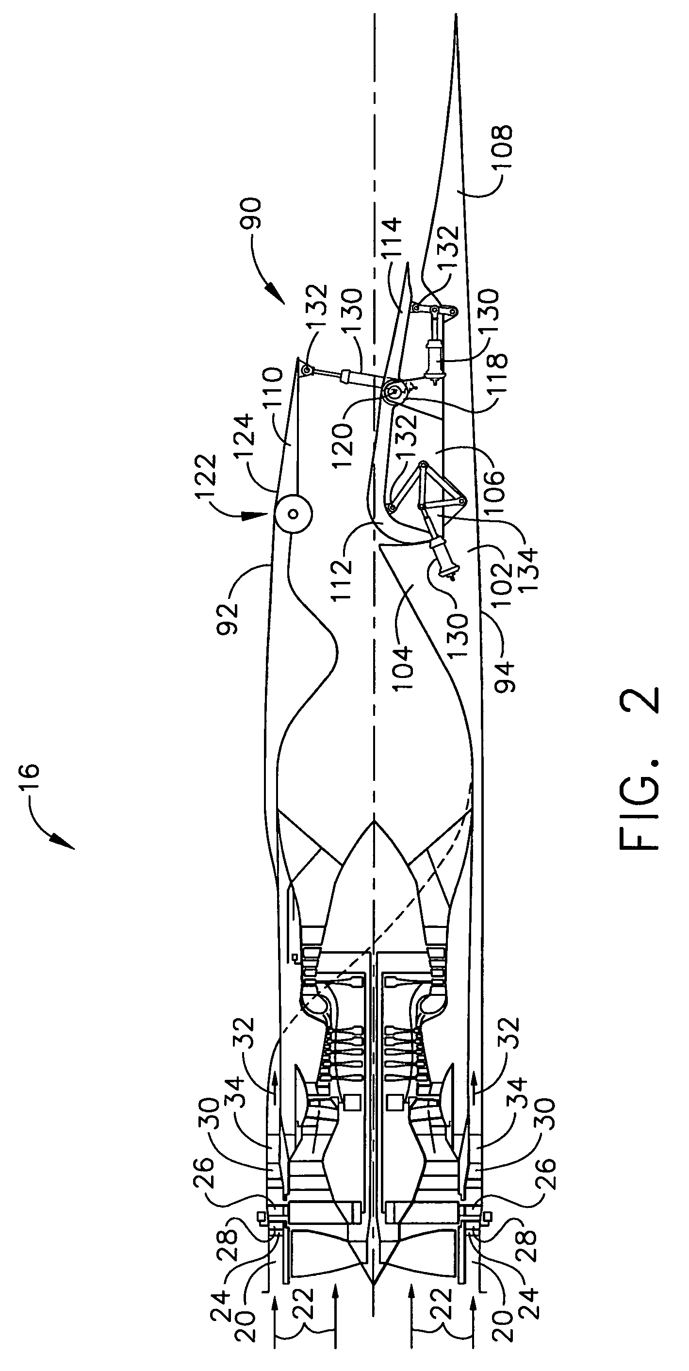
[0018]FIG. 2 is a schematic illustration of an exemplary “fan-on-blade” or FLADE engine 16 that may be used with jet aircraft 10 (shown in FIG. 1). Engine 16 includes a flade inlet 20 through which a relatively large percentage of an engine inlet airflow 22 enters during predetermined engine operations, such as during an aircraft takeoff. Airflow 22 enters flade inlet 20 and passes between an array of variable area inlet guide vanes 24. As illustrated in FIG. 2, inlet guide vanes 24 are actuated to their open position to direct large amounts of airflow toward a flade rotor 26.

[0019]Inlet...


PUM


Abstract

A method for adjusting a throat area of a jet aircraft exhaust nozzle assembly includes positioning a lower structure within a substantially rectangular nozzle assembly, coupling a ramp flap to the lower structure, and coupling an outer flap to the nozzle assembly such that movement of at least one of the ramp flap and the outer flap adjusts the throat area of the nozzle assembly.

Description

GOVERNMENT RIGHTS STATEMENT[0001]The United States Government may have rights in this invention pursuant to Contract No. MDA972-01-3-002.BACKGROUND OF THE INVENTION[0002]This invention relates generally to jet aircraft exhaust nozzles and more particularly, to methods and apparatus for adjusting a nozzle throat within a jet aircraft exhaust nozzle.[0003]At least some known engines include either a fixed exhaust nozzle system, such as is typical of commercial subsonic engines, or a variable exhaust nozzle system, such as is typical of supersonic military aircraft. The geometry of fixed nozzle systems are not kinematically changed or variable and as such may not operate as efficiently as variable exhaust nozzle systems.[0004]More specifically, variable geometry systems are configured to operate over a wide range of pressure ratios (P8 / Pamb) by adjusting a nozzle throat (A8) based on the demands of the engine cycle, and adjusting a nozzle area ratio (A9 / A8) to facilitate achieving a de...

Claims


Application Information

Patent Timeline
Patent Type & Authority Patents(United States)
IPC IPC(8): F02K3/075F02K1/12F02K1/00F02K3/00B64D33/04F02K1/15
CPCF02K1/123Y02T50/671Y02T50/60
Inventor RENGGLI, BERNARD JAMESJUMPER, MATTHEW WILSONPRICE, KENNETH DANIELKUCHAR, ANDREW PAUL
Owner GENERAL ELECTRIC CO
Why Eureka
Try Eureka